


PWM Interface (J100)
2-4
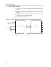
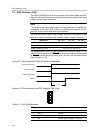
2.4 PWM Interface (J100)
This interface connects the TAS5110D6REF board to the PWM processor
module (e.g., TAS5026REF).
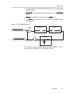
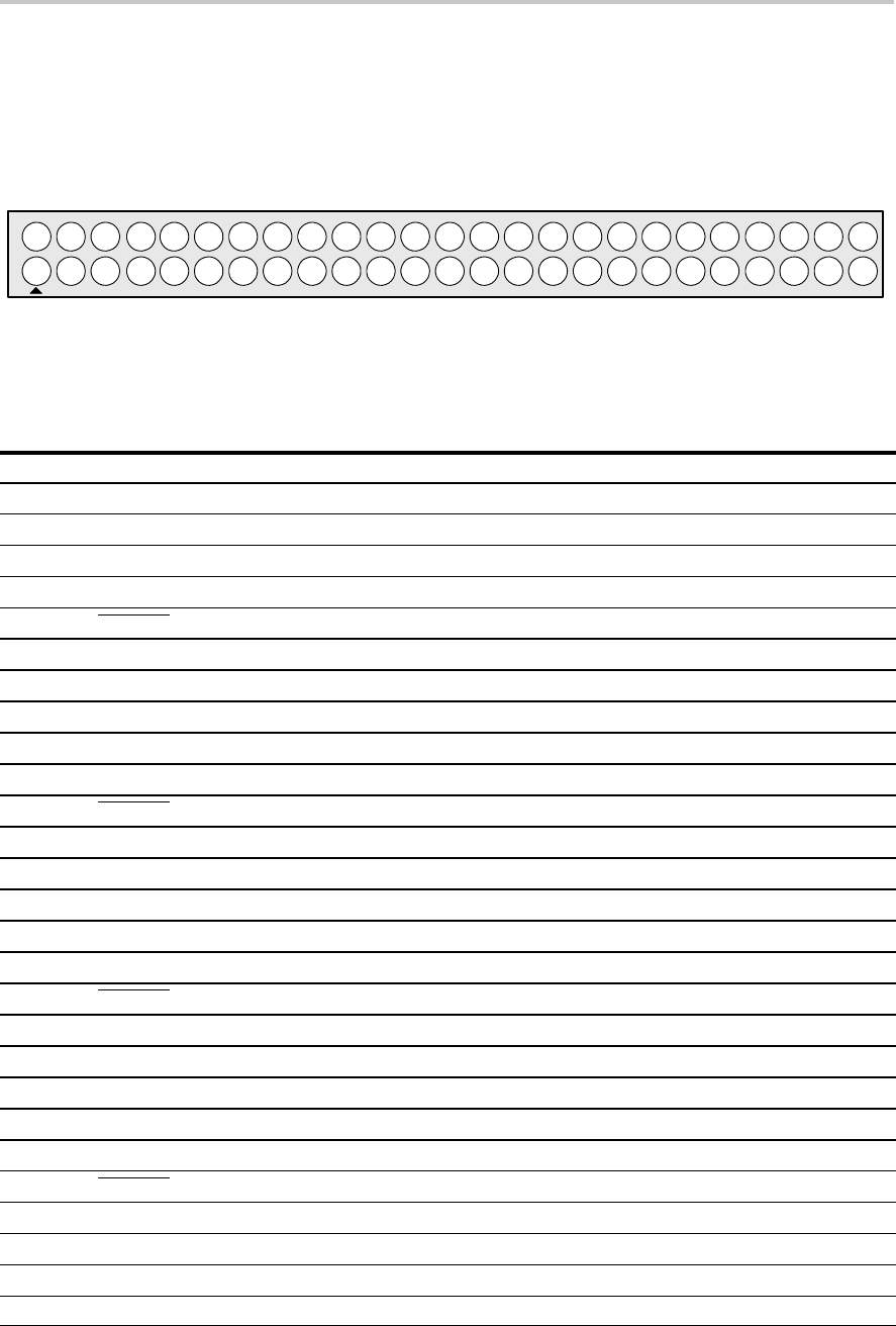
Figure 2–5. Pin Numbers at PWM Interface (J100)
2
31 5
64 8
97
10 12
1311 15
1614 18
1917
20 22
2321 25
2624 28
2927
30 32
3331 35
3634 38
3937
40 42
4341 45
4644 48
4947
50
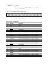
Connector: 50 positions, 2,54-mm pitch, double row IDC connector
(Multicomp MC9A12–5034).
Table 2–4.J100 Pin Description
Pin No. Net Name Description
01 V-HBRIDGE-CONTROL For future use
02 GND Ground
03 PWM–AP–1
Channel 1 PWM input (differential +) – positive H-bridge side
04 PWM–AM–1 Channel 1 PWM input (differential –) – positive H-bridge side
05 VALID–1 Valid channel 1
06 PWM–BM–1 Channel 1 PWM input (differential –) – negative H-bridge side
07 PWM–BP–1 Channel 1 PWM input (differential +) – negative H-bridge side
08 GND Ground
09 PWM–AP–2 Channel 2 PWM input (differential +) – positive H-bridge side
10 PWM–AM–2 Channel 2 PWM input (differential –) – positive H-bridge side
11 VALID–2 Valid channel 2
12 PWM–BM–2 Channel 2 PWM input (differential –) – negative H-bridge side
13 PWM–BP–2 Channel 2 PWM input (differential +) – negative H-bridge side
14 GND Ground
15 PWM–AP–3 Channel 3 PWM input (differential +) – positive H-bridge side
16 PWM–AM–3 Channel 3 PWM input (differential –) – positive H-bridge side
17 VALID–3 Valid channel 3
18 PWM–BM–3 Channel 3 PWM input (differential –) – negative H-bridge side
19 PWM–BP–3 Channel 3 PWM input (differential +) – negative H-bridge side
20 GND Ground
21 PWM–AP–4 Channel 4 PWM input (differential +) – positive H-bridge side
22 PWM–AM–4 Channel 4 PWM input (differential –) – positive H-bridge side
23 VALID–4 Valid channel 4
24 PWM–BM–4 Channel 4 PWM input (differential –) – negative H-bridge side
25 PWM–BP–4 Channel 4 PWM input (differential +) – negative H-bridge side
26 GND Ground
27 PWM–AP–5 Channel 5 PWM input (differential +) – positive H-bridge side