


PCB Key Map
1-3
Introduction
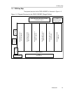
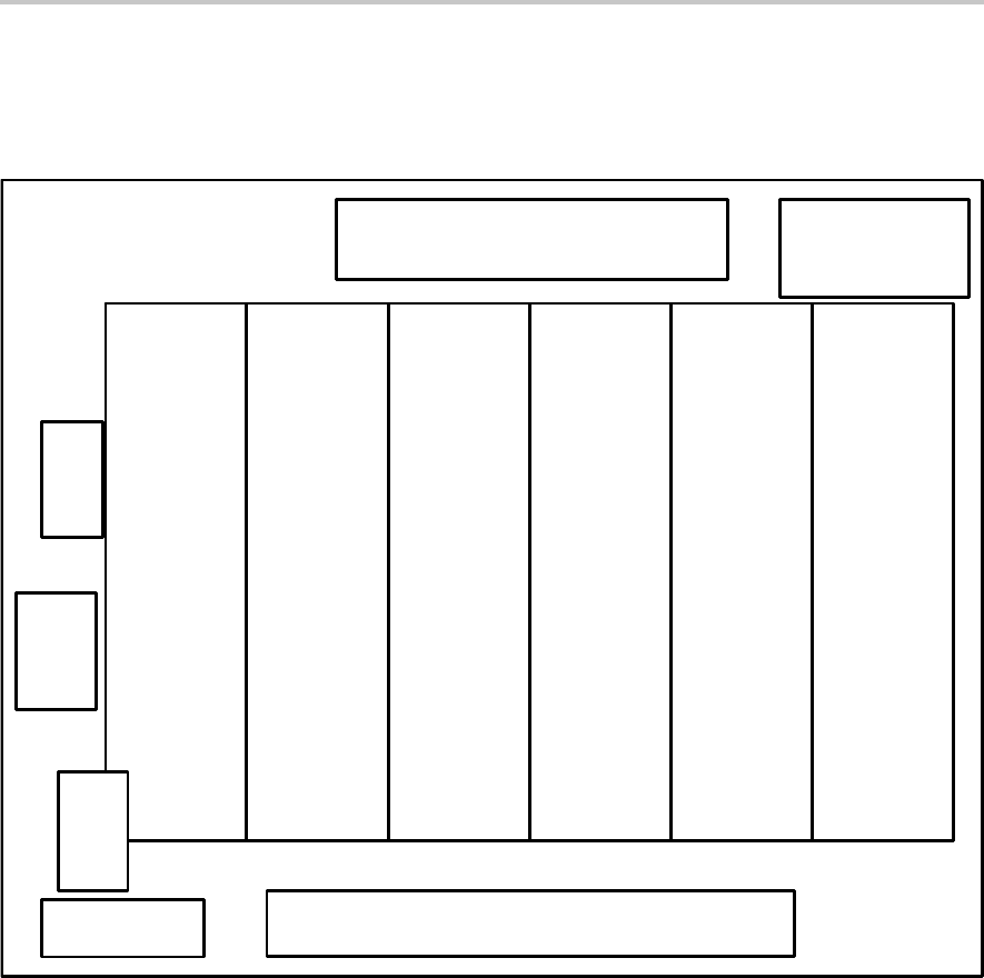
1.2 PCB Key Map
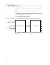
The physical structure for the TAS5110D6REF is illustrated in Figure 1–2.
Figure 1–2. Physical Structure for the TAS5110D6REF (Rough Outline)
J110
Subwoofer Output
(Line Level)
J240, J280, J340, J380, J440, and J480
Loudspeaker Outputs
J100
PWM Interface
J160
PSU Control
Interface
J150
3.3-V Linear
Regulator
LED Indicators
Output Stage Channel 1
Left Front Speaker
Output Stage Channel 2
Right Front Speaker
Output Stage Channel 3
Left Rear Speaker
Output Stage Channel 4
Right Rear Speaker
Output Stage Channel 5
Center Speaker
Output Stage Channel 6
Subwoofer
TAS5110D6REF
PSU Interface