


2 - Parts of the tape deck
16 TASCAM DA-45HR
[29]LOC 1
Pressing this key will locate the tape to the first mem-
ory location (set with this key in shifted mode). If the
tape is playing when this key is pressed, the tape will
resume playing when the location is reached, other-
wise it will stop.
When the key is pressed, the value stored in the first
location memory will flash on the right side of the
display (frames, program numbers and margin will
disappear while the tape is locating, and be restored
once location is complete).
If a pre-roll time has been set in the menu, pressing
this key will locate to the memory location minus the
pre-roll time.
[30]LOC 2
This key functions in exactly the same way asLOC 1
[29] above, except that the second location memory
is used rather than the first.
[31]SINGLE PLAY
The single play mode, when active, will play only
one program , i.e. when the next START ID is
encountered, playback will stop. When single play
mode is active, the display will show SINGLE
PLAY.
[32]SHIFT
This key is a latching key. When active, the indicator
beside and above the key lights, and the command
keys take on their shifted functions, as indicated by
the blue captions above them.
See 4, "Advanced functions" for details of these
shifted functions.
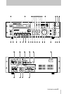
2.5 Rear panel
[33]DIGITAL (AES/EBU) INPUT/OUTPUT
These XLR connectors, wired in accordance with the
AES/EBU standard, provide digital audio input and
output facilities with the data being output in either
AES/EBU or SPDIF format (as selected in 3.6, "Dig-
ital output format"). The format of data received
(AES/EBU or SPDIF) is automatically detected.
[34]DIGITAL COAXIAL
These RCA connectors provide digital audio input
and output facilities with the data being output in
either AES/EBU or SPDIF format (as selected in 3.6,
"Digital output format"). The bit length is set using
the menu system (see 3.7, "Digital out word length").
The format of data received (AES/EBU or SPDIF) is
automatically detected.
[35]WORD IN and THRU (AUTO TERM)
These BNC connectors provide an input for an exter-
nal word clock (selected using the CLOCK switch
[4] set to the WORD position) at the IN connector,
which is re-transmitted from the THRU connector.
There is no need to provide any termination for the
THRU connector if no connection is made to it.
[36]CONTROL I/O
This 15-pin ’D’-sub connector is used for connection
to a suitably-equipped controller.
As well as the mode described in the table below, this
connector can also be used as a serial connector.
Please contact your TASCAM distributor for details
of this facility.
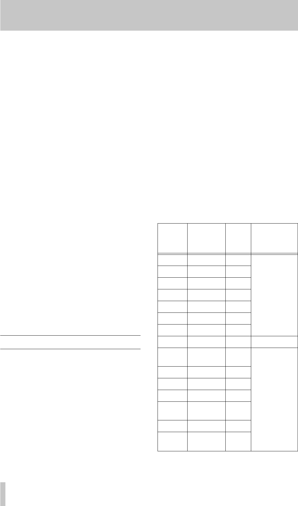
The pinouts of this connector are given below:
Pin
number
Signal
Direction
Function
1 STOP IN External com-
mand reception;
active when low
(at ground poten-
tial for 30 ms or
more)
2 FWD PLAY IN
3 F.FWD IN
4 REW IN
5 PAUSE IN
6 REC PLAY IN
7 SERIAL IN
8 Ground — —
9 FWD PLAY
TALLY
OUT Transmit trans-
port status indica-
tion signals in
open collector
(maximum allow-
able voltage 15 V
and maximum
allowable current
80 mA)
10 F.FWD TALLY OUT
11 REW TALLY OUT
12 STOP TALLY OUT
13 REC/PLAY
TALLY
OUT
14 PAUSE TALLY OUT
15 TAPE END
TALLY
a
a. See 3.14, "End tally signal"
OUT