


10
TASCAM DA-45HR
2 - Parts of the tape deck
NOTES
As well as providing details of the settings
made with switches, etc., this section also
provides the information necessary for basic
operations of the tape deck. Although the
operation of the transport keys, etc. will be
familiar, there are some additional features of
this tape deck, and the operation of these fea-
tures may differ slightly from the way in which
they are implemented on other units. Please
consult 2.3, "Tape controls" for full details of
such features and their operation.
The operation of the optional RC-D45 remote
control unit is explained in 5, "RC-D45 remote
control unit (option)".
The more commonly-used functions of the
function keys (below the display) which are
labeled in white above the keys are also
described in this section. The less commonly-
used functions, labeled in blue above the
keys, are described in 4, "Advanced func-
tions".
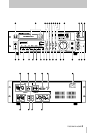
2.1 Power and display
[1] POWER switch
Push once to turn the power on, and again to turn the
power off.
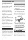
[2] Cassette tray and OPEN/CLOSE
button
Always load DAT cassettes in the way illustrated on
page 7.
Press the open/close button to open the tray. If a cas-
sette is already loaded, it will be unthreaded, and the
words
Tray Open!
will flash on the display.
After the tray is fully open, these words will be
shown (not flashing).
When the tray is open, and the open/close button is
pressed, the words
Tray Close
will flash on
the display. If a tape is correctly inserted in the tray
when it is closed, the display will show a counter
value.
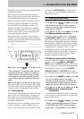
[3] Display window
The different modes available for display are
described more fully below (
COUNTER MODE
[21]
and
DISPLAY [24]
).
Above the tape counter in the display are two bar-
graph peak level meters which show either the level
of the input signals, or the level of the signals
recorded on tape, depending on the current status of
the transport.
Other indicators in the display provide information
on the current status of the tape deck and of the tape
(e.g. clock status, sampling frequency, repeat status,
and the various IDs encountered when a tape is being
replayed).
NOTE
In this manual, we use the term “program” to
describe part of a recording between two
START IDs. This is equivalent to the term
“track” on a CD or MD. Since the term “track”
is already established with another meaning
in analog tape recording technology, the term
“program” is used here instead.
2.2 Recording mode and source
switches, etc.
The following controls affect the recording mode,
and the selection of the signal source when making
recordings.
[4] CLOCK switch
Use this switch to select between
INT
(the tape
deck’s internal clock),
D-IN
(the word clock received
through the digital audio inputs— either
AES/EBU
or
COAXIAL
) or
WORD
(the word clock received
through the BNC word synchronization connector, as
described in 1.5.3, "Making word synchronization
connections").
When making recordings using digital audio connec-
tions from the source (the
INPUT SELECTOR
SWITCH [7]
is set to
DIGITAL
), this switch must be
set to
D-IN
or
WORD
, as appropriate. If the
CLOCK
switch is set to
INT
when digital recording is being
attempted, the display will show
CLKINTX
, and
no recording is possible.
WARNING
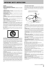
There must be one, and only one, word clock
source in a digital audio system. If there is
more than one word clock, or if a digital audio
device is not properly synchronized, damage
may be caused to speakers, etc.