


8 TASCAM 322
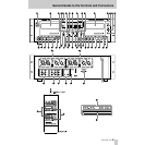
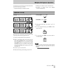
T DECK 2, INPUT and OUTPUT jacks : These
jacks are independent from deck 1 all the time.
NOTE
These jacks are only operational when the INPUT/
OUTPUT switch is set to the SEPARATE position.
U DECK 1/COMMON, INPUT and OUTPUT
jacks : When the INPUT/OUTPUT switch is set to
COMMON, inputs to deck 1 are taken into deck 2
as well, and outputs from deck 2 are sent to the
deck 1’s output jacks as well.
V CASCADE OUTPUT jacks : Used for dubbing
from a deck onto, or recording from an external
single source on multiple decks, as shown in the
diagram on page 13.
W EXT CONTROL jack : Used to connect a
multiple-322 system, as shown in the diagram on
page 12.
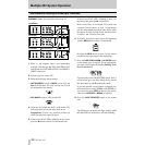
X REMOTE IN jack : For connection to the remote
control (RC-322A).
Y REMOTE (SERIAL) jacks : Used for control by
external devices using the RS-232C protocol.
Z DECK 2 INPUT, OUTPUT (L, R) connectors
and INPUT UNBAL/BAL switch : These are
balanced input and output connectors for DECK 2.
The pin assignment is 1=ground, 2=hot and 3=cold.
When the INPUT switch is set to the UNBAL
position, unbalanced signals may be input. Note
that this switch has no effect on the output signals
from these connectors, which are always balanced.
a DECK 1 INPUT, OUTPUT (L, R) connectors
and INPUT UNBAL/BAL switch : These are
balanced input and output connectors for DECK 1.
The pin assignment is 1=ground, 2=hot and 3=cold.
When the INPUT switch is set to the UNBAL
position, unbalanced signals may be input. Note
that this switch has no effect on the output signals
from these connectors, which are always balanced.
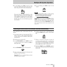
b CPS buttons : Can operate when the transport is
in Stop, Play Ready or Play modes to access
specific programs on the tape. See, also Using the
CPS Function, page 11.
c REC MUTE button : You can terminate recording
by pressing this button. A 4-second silence is then
recorded to the end of the recording. After this
interval, the deck goes into Record Ready mode.
All the other controls on the remote are duplicates
of the corresponding controls on the 322 unit.
NOTE
The remote unit is powered from the 322 unit.
Don’t attempt to open the lid on the remote unit.
Rear Panel
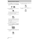
Options [LA-322]
RC-322A Remote Control Unit
General Guide to the Controls and Connectors