D13841.08
10.2007
34
Table of
Contents
Trademarks &
Copyright
Patents &
Disclaimers
Safety/
Environmental
To Get You
Up and Going
Using the 3G
Gateway
Viewing the
System Status
Configuring
the 3G Gateway
Maintenance
& Upgrade
Services
Dial Plan
Examples
Contact
Information
TANDBERG 3G Gateway
USER GUIDE
Configuring
the 3G Gateway
TANDBERG 3G GATEWAY
USER GUIDE
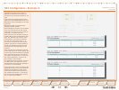
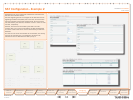
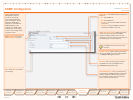
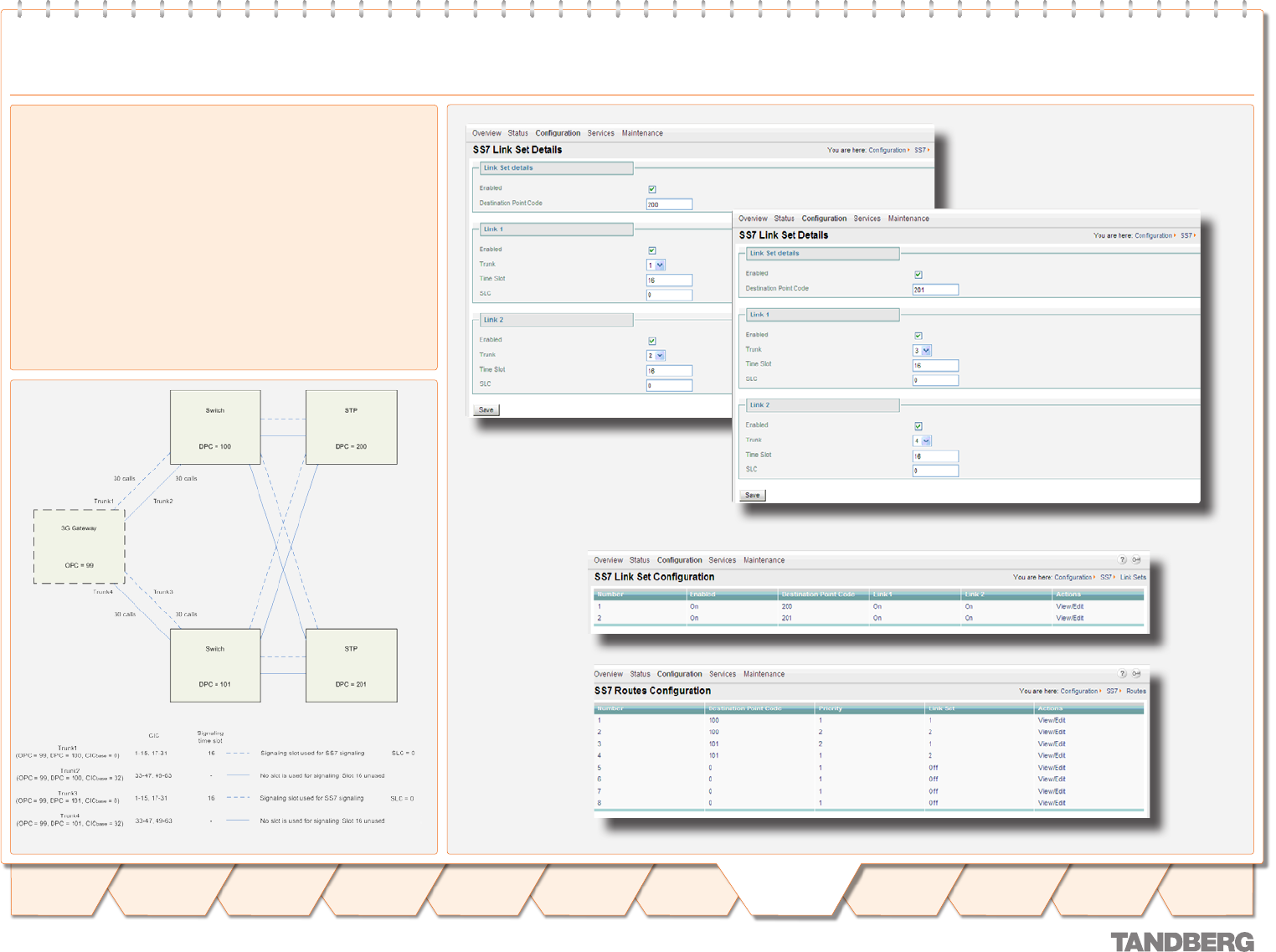
Suppose two out of four trunks are connected to one switch and
the other two to another switch.
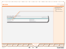
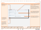
Now SS7 signalling fail-over is arranged via two switches and two
Signalling Transfer Points (STPs) over 2 link sets, as can be seen
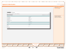
from the schematic and the SS7 window below. Since the trunks
are terminated by the switches, the DPCs of trunk 1 and 2 are 100
and 101, respectively.
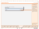
However, both links are terminated by the STPs. Link set 1
contains SS7 trunk 1 and is terminated by an STP with DCP 200.
Link set 2 contains SS7 trunk 3 and is terminated by an STP with
DCP 201.
For each link two routes are available to two switches, one directly
and one via an STP. Priority 1 is assigned to all direct links,
whereas all links via STPs have the lower priority 2.
SS7 Conguration – Example 2


