


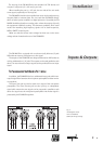
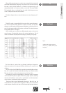

13
Peak
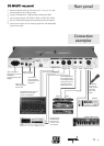
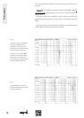
3
Phase reverse
4
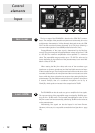
The INPUT section of the EQ MAGIX is equipped with a PEAK LED which
lights up approximately 3 dB below the value which would signify poten-
tial overdriving of the output (I
NSERT SEND). The headroom of the INPUT
stage is around 26.5 dB.
The P
EAK LED does not indicate the overdriving limit of the PARAMETRIC
stage, as this varies, depending on the values set on the EQ. The PARAMETRIC
stage has a lower headroom limit (+22 dB) when the stage is activated and
the B
OOST/CUT control is on 0dB. If the PEAK LED lights up, and the
P
ARAMETRIC stage is in use, the preamplification (MIC/LINE) must be
decreased.
Pressing the phase switch (P
HASE REVERSE) inverts the polarity of the
microphone signal. When the switch has not been pressed (status LED is
off), the polarity is »in phase«. Pressing the switch means that the polarity
is »out of phase«.
Phase inversion can be used for a number of different reasons:
1. If, for example, the microphone signal of a singer or speaker is pream-
plified in the EQ MAGIX and the monitor signal is folded back to the head-
phones, the singer or speaker cannot hear himself very well. Pressing the
phase switch inverts the polarity of the microphone and consequently, of
the headphone signal, and the singer or speaker can then hear himself on
his headphones without having to increase the level.
2. The phase inversion feature is also very useful when the polarity of
the XLR input jack has to be inverted to match the polarity of the micro-
phone or the microphone cable. The pin assigment of the XLR connector is
as follows: Pin 2 = hot (+) and Pin 3 = cold (-).
3. Sometimes it is desirable to swop the polarity of a microphone
because of the sound.
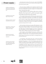
Condensor microphones require a supply voltage of 48V DC which
supplies the microphone via the balanced audio lines (pins 2 and 3).
When the supply voltage is switched on, a phantom circuit is formed
whereby the 48V DC supply voltage is applied simultaneously to the two
supply lines (+/-) of the microphone and fed back via the cable screen.
There is no DC voltage between the two modulation lines which is why
dynamic microphones can be used when the phantom voltage is switched
on, without this doing the microphones any harm.
The influences of noise voltages which can superpose the DC supply
voltage such as hum loops and parasitic currents in the cable screen are
reduced by the phantom power supply. Moreover, this type of connection is
particularly resistant towards RF.
As there is no potential difference between the +/- supply lines, the
connection technique of the phantom supply is compatible with moving coil
and ribbon microphones.
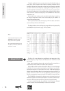
48 V
5
Phantom power supply according
to
DIN 45 596 / IEC 268-15
Input