


– 20 –
BD board
TP (XPCK)
+
–
frequency counter
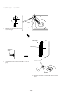
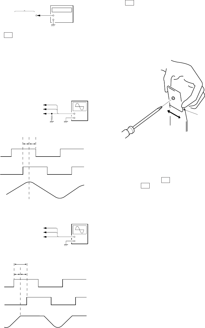
Procedure:
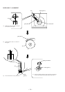
1. Connect the oscilloscope to Pins 1, 2, and 4 of CN506 of
the MAIN board. Also connect a 1 kΩ resistor to Pin 4 at the
same time. (Connection 1)
2. Check that no discs are loaded in the unit, and press the
I/u button while pressing the [INPUT] button.
3. The rotary table will continue rotating in the clockwise direc-
tion.
4. Observe the waveform at that time on the oscilloscope.
5. Loosen the screw securing the LUMINOUS board slightly.
6. Slide the LUMINOUS board to the left and right so that the
peak of the D0 waveform is at the center between the descend-
ing point of the T1 waveform and ascending point of the T2
waveform. (Waveform 1) After adjusting, apply locking com-
pound.
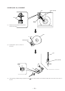
7. Disconnect the resistor connected to Pin 4 of CN506 of the
MAIN board. (Connection 2)
8. Observe the waveform on the oscilloscope. (Waveform 2)
9. Adjust RV501 of the MAIN board so that the waveform on the
oscilloscope satisfies the following adjustment value.
10. After the adjustment, load a disc only in slit 1, close the front
cover, and press the I/u button to turn off the power.
11. Press the
I/u
button while pressing the
[PUSHENTER] button
to turn on the power.
12. If the rotary table makes round, and “YES” is displayed on the
fluorescent indicator tube after it stops, it means that the ad-
justment has been performed properly.
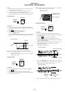
Adjustment value:
At the shoulder part of waveform D1, T1 becomes H and T2 be-
comes L, and at the same time, the Y width must not be smaller
than 1/4 of the Z width.
In order to satisfy this value more easily, adjust so that X=Y ap-
proximately and observe the deviation of the waveform.
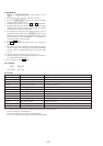
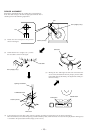
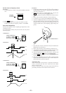
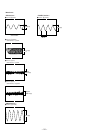
RF PLL Free-run Frequency Check
Procedure :
1. Connect frequency counter to test point TP (XPCK) with lead
wire.
2. Turn I/u button on.
3. Put the disc (YEDS-18) in to play the number five track.
Confirm that reading on frequency counter is 4.3218MHz.
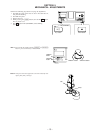
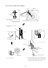
Disc Sensor Adjustment
Perform this adjustment after completing all adjustments of the
mechanism section.
If not performed accurately, the presence of the disc may not be
detected properly.
Connection 1:
Waveform 1:
Connection 2:
Waveform 2
+
–
oscilloscop
e
CN506 of MAIN board
T1: Pin
1
(T. SENS 1)
T2: Pin
2
(T. SENS 2)
D0: Pin
4
(D. SENS)
1 k
Ω
AB
T1
T2
D0
+
–
oscilloscop
e
CN506 of MAIN board
T1: Pin
1
(T. SENS 1)
T2: Pin
2
(T. SENS 2)
D0: Pin
4
(D. SENS)
Z
XY
T1
T2
D1
LUMINOUS boar
d