


– 19 –
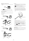
Note: A clear RF signal waveform means that the shape “◊” can be clearly
distinguished at the center of the waveform.
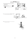
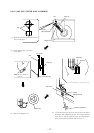
E-F Balance Check
Procedure :
1. Connect oscilloscpe to test point TP (TE) on BD board.
2. Connect the test point TP (ADJ) on MAIN board to the ground
with a lead wire.
3. Turn the I/u button on to set the ADJ mode.
4. Put disc (YEDS-18) in to play the number five track.
5. Press the [GROUP3] button. (The tracking servo and the sled-
ding servo are turned OFF.)
6. Check the level B of the oscilliscope's waveform and the A
(DC voltage) of the center of the Traverse waveform.
Confirm the following :
A/B x 100 = less than ± 22%
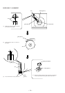
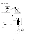
7. Press the
[GROUP8] button. (The tracking servo and sled-
ding servo are turned ON.) Confirm the C (DC voltage) is
almost equal to the A (DC voltage) is step 6.
8. Disconnect the lead wire of TP (ADJ) connected in step 1.
SECTION 6
ELECTRICAL ADJUSTMENTS
Note:
1. CD Block is basically designed to operate without adjustment. There-
fore, check each item in order given.
2. Use YEDS-18 disc (3-702-101-01) unless otherwise indicated.
3. Use an oscilloscope with more than 10MΩ impedance.
4. Clean the object lens by an applicator with neutral detergent when the
signal level is low than specified value with the following checks.
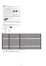
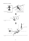
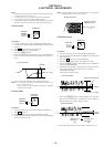
S-Curve Check
Procedure :
1. Connect oscilloscope to test point TP (FE1) on BD board.
2. Connect test point TP (ADJ) on MAIN board to ground with
lead wire.
3. Turn I/u button on to set the ADJ mode.
4. Put disc (YEDS-18) in and playback.
Press the [CHECK] button.
5. Check the oscilloscope waveform (S-curve) is symmetrical be-
tween A and B. And confirm peak to peak level within 3 ± 1
Vp-p.
6. After check, remove the lead wire connected in step 2.
Note: • Try to measure several times to make sure than the ratio of A : B
or B : A is more than 10 : 7.
• Take sweep time as long as possible and light up the brightness
to obtain best waveform.
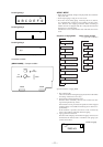
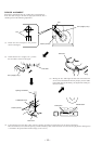
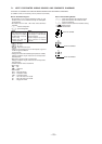
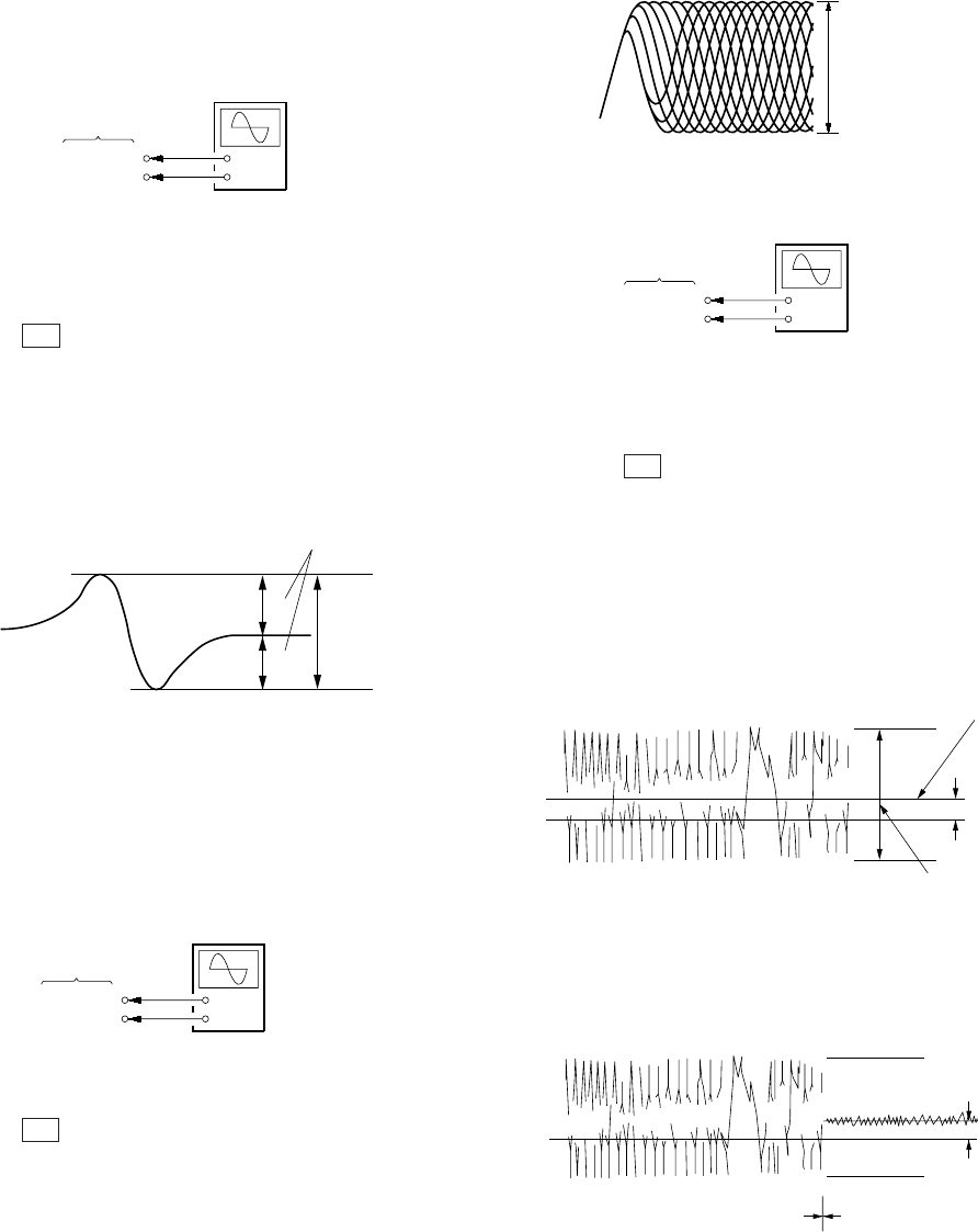
RF Level Check
Procedure :
1. Connect oscilloscope to test point TP (RFO) on BD board.
2. Turn I/u button on.
3. Put disc (YEDS-18) in to play the number five track.
4. Confirm that oscilloscope waveform is clear and check RF sig-
nal level is correct or not.
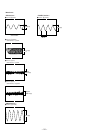
BD board
TP (FE1)
TP (VC)
+
–
oscilloscop
e
S-curve waveform
symmetry
A
B
within 3
±
1 Vp-p
BD board
TP (RFO)
TP (VC)
+
–
oscilloscope
(AC range)
VOLT/DIV: 200 m
V
TIME/DIV: 500 ns
level: 1.2 Vp-p
RF signal waveform
+0.25
–0.20
BD board
TP (TE)
TP (VC)
+
–
oscilloscope
Traverse waveform
Center of the waveform
B
A (DC voltage
)
level: 1.3
±
0.6 Vp-p
0 V
Traverse waveform
C (DC
voltage)
0 V
Tracking servo
Sled servo
OFF
Tracking servo
Sled servo
ON