


– 10 –
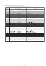
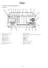
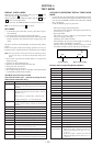
Button Button Number or Display
CLEAR 3
CHECK 4
± (AMS) 5
≠ (AMS) 6
PUSH ENTER 7
§
(OPEN/CLOSE)
9
INPUT 10
MEMO SEARCH 11
I/u 18
TIME/TEXT 19
GROUP FILE 20
GROUP 8 21
GROUP 7 22
GROUP 6 23
GROUP 5 24
REPEAT 27
PROGRAM 28
SHUFFLE 29
CONTINUE 30
GROUP 4 31
GROUP 3 32
GROUP 2 33
GROUP 1 34
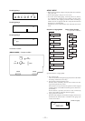
· All lit (LED lit)
P Partial lighting 1 (LED lit)
p Partial lighting 2
DISC/ Partial lighting 3
CHARACTER • When the jog dial is rotated to the right, the
GROUP LEDs light up in the order of 1 → 2..8
→ 2nd → 1.
• When the jog dial is rotated to the left, the
GROUP LEDs light up in the order of 8 → 7..1
→ 2nd → 8.
SECTION 4
TEST MODE
DISPLAY CHECK MODE
With the power turned off (standby state), press the I/u button
while pressing the P (pause) button.
All FL segments and grids light up together with the · (play),
P (pause), and standby LEDs.
At the same time, the GROUP LEDs are scanned one by one.
Note: To exit this mode, press the p (stop) button.
ADJ MODE
1. Turn ON the power of the unit, set disc to disc table, and per-
form chucking.
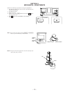
2. Disconnect the power supply plug from the outlet.
3. To set ADJ mode, connect the test point (TP: ADJ) of the MAIN
board to Ground, and connect the power supply plug to the
outlet.
The power will turn on automatically, and the first track will be
played.
In this mode, table rotation and loading operations are not per-
formed because it is taken that the disc has already been chucked.
Note: The same operations are also performed in the following when the
test point (TP: ADJ) is connected to Ground after turning on the
power.
• Direct search (movement of sledding motor) is not performed
during accessing
• Ignored even when GFS becomes L
• Ignored even when the Q data cannot be read
• Focus gain does not decrease
• Spindle gain does not decrease
• Servo related settings can be set manually and checked (Refer
to ADJ Mode Special Functions Table)
ADJ Mode Special Functions Table
(The buttons shown with ( ) function by using the sup-
plied remote commander only)
KEY AND FLUORESCENT DISPLAY TUBE CHECK
MODE
1. Connect the test point (TP:AFADJ) of the MAIN board to the
Ground, and insert the power plug to the outlet to set this mode.
First, the external SRAM is checked, and if abnormal, “SRAM
NG” is displayed.
If OK, the following steps are performed.
* Fluorescent Display Tube Check Mode
The whole fluorescent display tube lights up when the con-
nection in step 1 is made.
* Key Check Mode
This mode is set when a button is pressed after the whole
fluorescent display tube lights.
All buttons have a button number.
When a button is pressed, the counter display is counted up,
and the number of that button is displayed.
However, the counter display will only count up to 26, but
the number of buttons pressed will always be displayed.
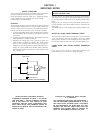
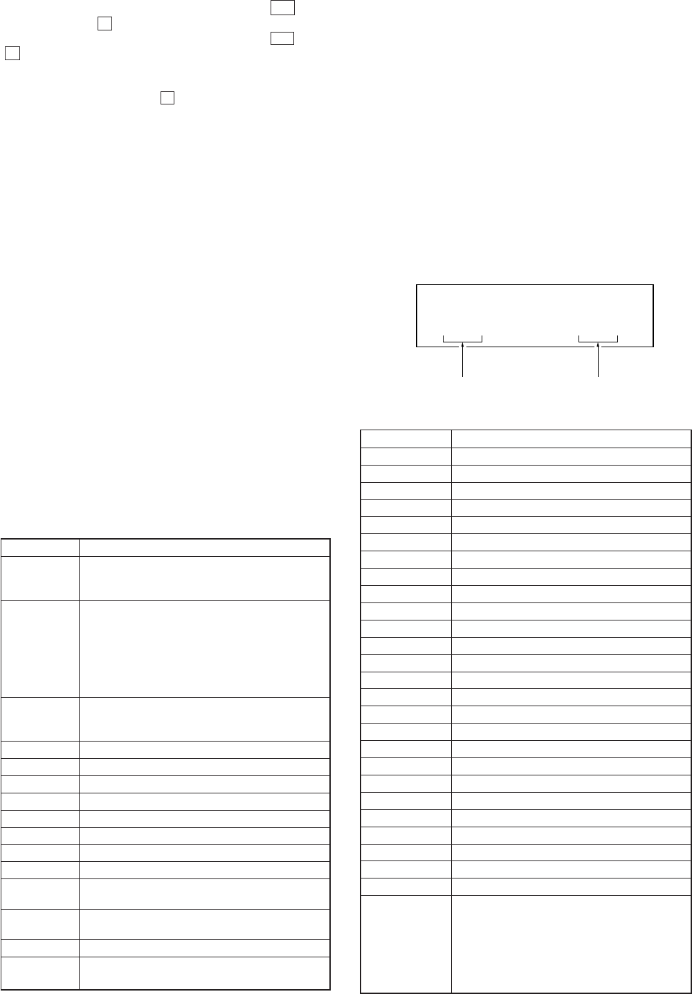
** **
O
Counter display
Button number display
Buttons and Corresponding Button Numbers
Button Button Number or Display
CONTINUE Servo average display
Displays VC, FE, RF, TE and traverse in hexadecimal
numbers
SHUFFLE Focus bias display
Each time this is pressed, the focus bias is switched
between 1 and 2
1
Bias actually set Optimum bias Minimum jitter
2
U:Upper aliasing bias L:Lower aliasing bias
PROGRAM Auto gain display
Displays focus, tracking, sledding in hexadecimal
numbers
GROUP 1 (1) Increases the focus bias in 8 steps.
GROUP 2 (2) Sets the focus bias in the middle of aliasing.
GROUP 3 (3) Turns off the tracking and sledding servo
GROUP 4 (4) Returns the auto gain to the initial value (30)
GROUP 5 (5) Turns off the focus servo
GROUP 6 (6) Decreases the focus bias in 8 steps.
GROUP 7 (7) Re-adjusts the focus bias
GROUP 8 (8) Turns on the tracking and sledding servo
(9) Switches the focus servo gain between normal and down
FG. norm: normal, FG. down: down
(10/0) Sets the focus bias to 0 (no bias)
Next, displays the jitter measured at the focus bias set
CHECK S-curve observation mode
CLEAR Automatic eccentric measurement
The results of measurement is displayed in mm directly.