26
US
S VIDEO S VIDEO
ANALOG ANALOG
OUT OUTIN
OUT IN
L
R
L
R
YP
B
/C
B
P
R
/C
R
IN
IN
S VIDEO S VIDEO
OUT
OPTICAL
ANALOG
IN
IN
VIDEO
TV/SAT
AUX
COMPONENT VIDEO OUT
MONITOR
INTERLACE
SELECTABLE
SCAN SELECT
YP
B
/C
B
P
R
/C
R
COMPONENT VIDEO IN
DIGITAL
MD/DAT
OPTICAL IN
TV/SAT AUX
COAXIAL IN
ANALOG
OUT
FRONTCENTER
SPEAKERS
IMPEDANCE USE 6–16Ω
SUB
WOOFER
LR
SURROUND
LR
COAXIAL
AM
FM
75Ω
ANTENNA
R
S VIDEO
IN
S VIDEO
IN
AUDIO
IN
L
IN INOUT OUT OUT
OUTPUT
INPUT
OPTICAL
R
L
S VIDEO
IN
AUDIO
IN
R
L
S VIDEO
IN
AUDIO
IN
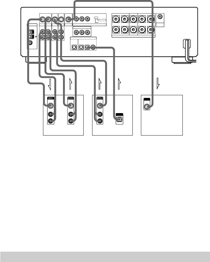
If you connect a digital satellite receiver with the OPTICAL OUT jack
The digital satellite receiver can be connected to the TV/SAT (OPTICAL IN) jack instead of the
ANALOG IN L/R jacks of the receiver.
The receiver can accept both the digital and analog signals. Digital signals have priority over
analog signals. If the digital signal ceases, the analog signal will be processed after 2 seconds.
If you connect a digital satellite receiver without the OPTICAL OUT jack
Connect the digital satellite receiver to the S VIDEO IN and ANALOG IN L/R jacks only of the
receiver.
If you connect a component with the COMPONENT VIDEO OUT jacks (Y, P
B/CB,
P
R/CR)
Connect the component to the COMPONENT VIDEO IN jacks (Y, P
B/CB, PR/CR) of the
receiver.
Connecting the AC Power Cord (mains lead)
Before connecting the AC power cord (mains lead) of this receiver to a wall outlet (mains),
connect the speakers to the receiver (see page 21).
Connect the AC power cord (mains lead) of your TV/video components to a wall outlet (mains).
VCR Digital satellite receiver TV monitor


