


Getting Started
5
EN
3-859-278-12(1)
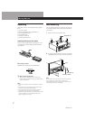
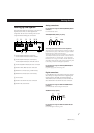
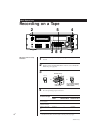
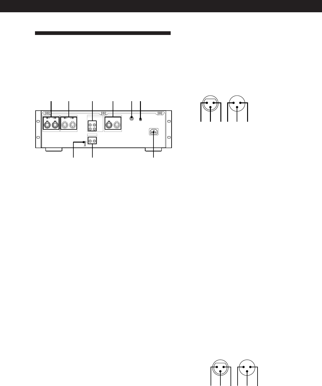
Hooking Up the System
This section describes how to hook up your deck to an
amplifier, stereo mixer, or other digital audio
components. Be sure to turn off the power to each
component before making the connections.
DIGITAL IN/OUT
DIGITAL
IN/OUT
AES/EBU COAXIAL
COAXIAL
IN OUT
IN OUT
CH-1 (L)
CH-2 (R)
DIGITAL IN/OUT
REMOTE 1 REMOTE 2
⁄AC IN
ANALOG(UNBALANCE)
AES/EBU
IN OUT
ANALOG(BALANCE) OUT
LEVEL
CH-1 (L) CH-2 (R)
ANALOG(BALANCE) IN
LEVEL
CH-1 (L) CH-2 (R)
1 2 4 53 6
79 8
1 ANALOG(BALANCE) IN connectors/
ANALOG(BALANCE) IN LEVEL controls
2 ANALOG(BALANCE) OUT connectors/
ANALOG(BALANCE) OUT LEVEL controls
3 ANALOG(UNBALANCE) IN/OUT connectors
4 DIGITAL AES/EBU IN/OUT connectors
5 REMOTE 1 connector (For parallel remote)
6 REMOTE 2 connector (For serial remote)
7 AC IN socket
8 DIGITAL COAXIAL IN/OUT connectors
9 DIGITAL IN/OUT switch
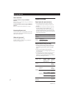
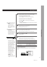
Analog connections
For connections through the ANALOG(BALANCE) IN/OUT
connectors
Use XLR balanced cables.
ANALOG(BALANCE) IN/OUT pin polarity
23 1
OUTIN
132
1:GND
2:HOT
3:COLD
The analog input/output reference level adjustment
The analog input/output reference level during recording or
playback is factory set to +4 dBs within a range of –20 dB to
the full bit level for both input and output.
To lower the reference level, use a screwdriver to adjust the
ANALOG(BALANCE) IN/OUT LEVEL controls on the rear
panel for both CH-1 (L) and CH-2 (R). You can adjust the
reference level in a range of +4 dBs to –12 dBs. Make sure to
set the REC LEVEL CH-1(L)/2(R) controls on the front panel
to the center point before making this adjustment.
For connections through the ANALOG(UNBALANCE) IN/
OUT connectors
Use phono-plug audio connecting cords.
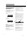
Digital connections
Use the DIGITAL IN/OUT switch on the rear panel to
select the input/output connectors for digital signals.
Set the switch to AES/EBU to select the DIGITAL
AES/EBU IN/OUT connectors; set it to COAXIAL to
select the DIGITAL COAXIAL IN/OUT connectors.
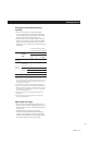
For connections through the DIGITAL AES/EBU IN/OUT
connectors
Use XLR balanced cables for digital connections.
AES/EBU IN/OUT pin polarity
23 1
OUTIN
132
1:GND
2:HOT
3:COLD
For connections through the DIGITAL COAXIAL IN/OUT
connectors
Use coaxial digital connecting cords.