


3-859-278-11(1)
Additional Information
28
EN
KEY PROTECT
AUTO
MIN MAX
OFFWIRED
WIRELESS
REMOTE
POWER
Ø ON ø OFF
PHONE LEVEL
PHONES
•
•
•
•
•
•
•
•
•
•
•
RENUMBER
REHEARSAL
REHEARSAL
WRITE
WRITE
ERASE
ERASE
REPEAT
SKIP PLAY
LOCATE
MODE
COUNTER RESET
MARGIN RESET
PREVIOUS
AMS
=
OPEN/CLOSE
6
NEXT
+
STOP
p
REW
0
PLAY
(
FF
)
PAUSE
P
REC MUTE
R
REC
r
MENU
DATASHUTTLE
CH-1(L)
r
SET
MARK
010
ANALOGDIGITAL
INPUT
REC LEVEL
•
•
•
•
•
•
•
•
•
•
•
OFF ON
SBM
UNBALANCEBALANCE
ANALOG INPUT
STANDARD
48k 44.1k
LONG
REC MODE
CH-2(R)
010
•
•
•
•
•
•
•
•
•
•
•
START ID
SKIP ID
INPUT
MONITOR
FADER
OFF ON
KEY PROTECT
23456781
OPEN
GND
8
67
13
45
2
y
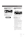
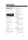
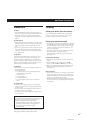
Remote Control Function Using
a Parallel Remote Connector
You can operate the deck with a parallel remote control
that uses a switch box connected to the REMOTE 1
connector on the rear panel.
Using the REMOTE 1 connector
When operating the deck with a parallel remote
control, set the REMOTE switch on the front panel to
WIRED.
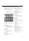
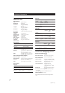
The pin numbers and pin assignments for the
REMOTE 1 connector on the rear panel are as follows:
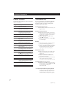
DIN connector (8 pin)
Inputs
MODE1
(playback)
MODE2
(recording)
H-level constant L-level constant
2 H-STOP/L-PLAY
3 L-STOP L-START ID
WRITE
4 L-PLAY L-PLAY
5 L-REW L-PAUSE
6
L-FF
L-REC
Status
output
7
H-STOP
H-REC-PAUSE
8
H-PLAY H-REC
Case
GND
Case
Pin No
L-STOP
GND
Command inputs H: OPEN (off impedance: 30 kilohms or
more)
L: GND short (on impedance: 100 ohms
or less)
Status output H: approx 2V (I=15mA)
L: OPEN (High impedance)
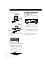
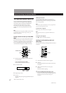
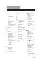
Connection diagram (MODE 1)
Case
Command input
switch
Status output
display (LED)
Notes
• When using MODE 2, use pin number 1 for GND.
• By keeping the input to pin number 1 constant at either H-
level or L-level determines whether pin numbers 2 to 8 are
in MODE 1 (playback) or MODE 2 (recording).
• In MODE 1, pin number 2 may be used for fader-start
function.
• For pin numbers 2 to 6 pin, input to smaller numbers take
priority.
• Anti-chattering measures should be taken for the
command input switches.
• Status output (pin numbers 7 and 8) is specially provided
for driving a single LED. If more current is needed, use an
additional drive circuit or electric power supply.
• Do not switch input to pin number 1 (MODE 1 and MODE
2) while the deck is playing or recording. This may result
in mis-operation of the deck.
Additional Information
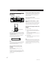
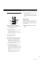
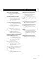
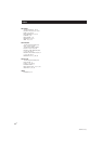
Disabling Button Operations
(Key Protect Function)
(PCM-R700 Only)
You can disable certain button operations so that the
buttons do not work during, for instance, recording.
1
All of these buttons and dials
are disabled.
Set KEY PROTECT to ON.