


20
MZ-NF610
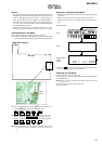
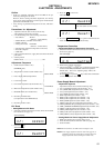
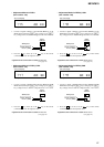
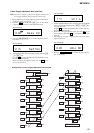
• Adjustment Method of VC2_LOW
(item number: 743)
1. Connect a digital voltmeter to the TP1905 (VCOUT) on the
MAIN board, and adjust [VOL +] key (voltage up) or [VOL --]
key (voltage down) so that the voltage becomes 2.30 ± 0.01V.
2. Press the X key on the set or the key on the remote
commander to write the adjusted value.
Adjustment and Connection Location:MAIN board
(see page 24)
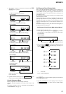
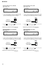
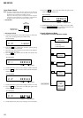
• Adjustment Method of VC2_HIGH
(item number: 744)
1. Connect a digital voltmeter to the TP1905 (VCOUT) on the
MAIN board, and adjust
[VOL +] key (voltage up) or [VOL --]
key (voltage down) so that the voltage becomes 2.55 ± 0.01V.
2. Press the X key on the set or the key on the remote
commander to write the adjusted value.
Adjustment and Connection Location:MAIN board
(see page 24)
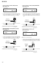
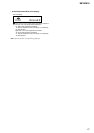
• Adjustment Method of VC1_LOW (PB)
(item number: 741)
1. Connect a digital voltmeter to the TP1928 (VCO1) on the MAIN
board, and adjust
[VOL +] key (voltage up) or [VOL --] key (volt-
age down) so that the voltage becomes 2.35 ± 0.05V.
2. Press the X key on the set or the key on the remote
commander to write the adjusted value.
Adjustment and Connection Location:MAIN board
(see page 24)
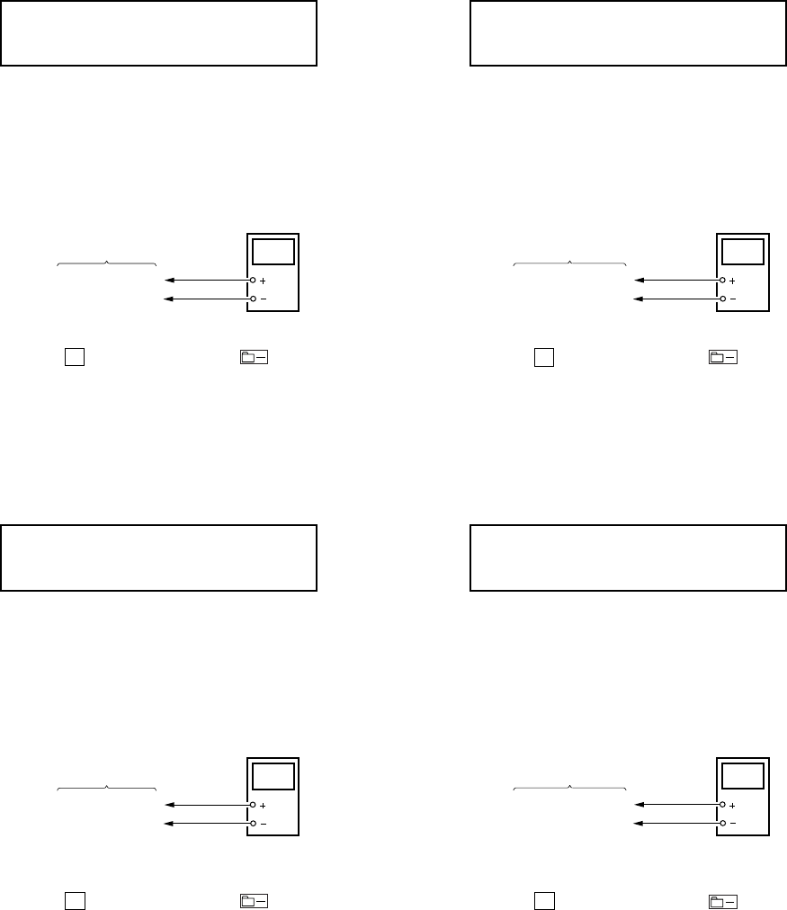
• Adjustment Method of VC1_HIGH (REC)
(item number: 742)
1. Connect a digital voltmeter to the TP1928 (VCO1) on the
MAIN board, and adjust
[VOL +] key (voltage up) or [VOL --]
key (voltage down) so that the voltage becomes 2.50 ± 0.05V.
2. Press the X key on the set or the key on the remote
commander to write the adjusted value.
Adjustment and Connection Location:MAIN board
(see page 24)
digital
voltmete
r
MAIN board
TP1928 (VCO1)
TP1311 (GND)
digital
voltmeter
TP1905 (VCOUT)
TP1311 (GND)
MAIN board
digital
voltmete
r
MAIN board
TP1928 (VCO1)
TP1311 (GND)
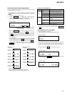
7 41 A D * *
**
: Adjusted value
Set LCD display
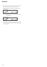
7 42 A D * *
**
: Adjusted value
Set LCD display
7 43 A D * *
**
: Adjusted value
Set LCD display
digital
voltmeter
TP1905 (VCOUT)
TP1311 (GND)
MAIN board
7 44 A D * *
**
: Adjusted value
Set LCD display