


19
MZ-NF610
3. Press the X key once more.
4. Press the xCANCEL/CHG key to quit the manual mode, and
return to the test mode (display check mode).
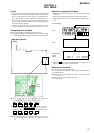
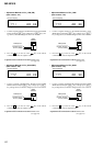
Temparature Correction
• Adjustment Method of Temperature Correction
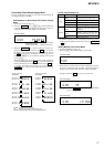
1. Select the manual mode of the test mode, and set the item num-
ber 015 (see page 14).
2. Measure the ambient temperature.
3. Adjust with [VOL +] or [VOL --] key so that the adjusted value
(hexadecimal value) becomes the ambient temperature.
(Initial value : 19h = 25˚C, Adjusting range : 80h to 7fh
(–128˚C to +127˚C))
4. Press the
X key
or press the key on the remote commander
to write the adjusted value.
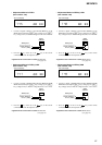
Power Supply Manual Adjustment
• Adjustment sequence
Adjustment must be done with the following steps.
1. VC1_LOW (PB) adjustment (item number : 741)
2. VC1_HIGH (REC) adjustment (item number : 742)
3. VC2_LOW adjustment (item number : 743)
4. VC2_HIGH adjustment (item number : 744)
5. REG1 adjustment (item number : 745)
6. REG3_LOW1 adjustment (item number : 747)
7. REG3_LOW2 adjustment (item number : 748)
8. REG3_HIGH adjustment (item number : 749)
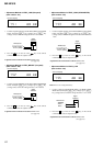
9. VREC_LOW (X2 speed) adjustment (item number : 751)
10. VREC_MIDDLE (X4 speed)adjustment (item number : 752)
11. VREC_HIGH (HEAD MOTOR) adjustment (item number : 753)
12. CHGV_LOW adjustment (item number : 755)
13. CHGV_HIGH adjustment (item number : 756)
14. CHGI_LOW (current) adjustment (item number : 757)
15. CHGI_HIGH (current) adjustment (item number : 758)
• Setting Method of Power Supply Manual Adjustment
1. Make sure that the power supply voltage is 3V.
2. Select the manual mode of the test mode (see page 14).
3. Set item number.
Note1: BATT- terminal is not GND when AC adaptor is used.
Note2: Power supply adjustment auto item feed mode (page 25) is
available to perform the temperature Correction and Power
Supply Adjustment without entering the manual mode.
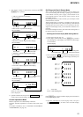
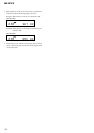
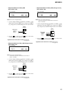
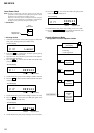
NV Reset
• Setting Method of NV Reset
1. Select the manual mode of the test mode, and set item number
021 NV Reset (see page 14).
2. Press the
X key.
SECTION 5
ELECTRICAL ADJUSTMENTS
Outline
• In this set, automatic adjustment of CD and MO can be per-
formed by entering the test mode.
However, before starting automatic adjustment, the memory
clear, power supply adjustment, and laser power check must be
performed in the manual mode.
•A key having no particular description in the text, indicates a
set key.
Precautions for Adjustment
1. Adjustment must be done in the test mode only.
After adjusting, release the test mode.
2. Use the following tools and measuring instruments.
•Test CD disc TDYS-1
(Part No. : 4-963-646-01)
• SONY MO disc available on the market
• Digital voltmeter
• Laser power meter LPM-8001
(Part No. : J-2501-046-A)
•Thermometer (using the Temperature Correction)
• Personal computer
• USB cable
3. Unless specified otherwise, supply DC 3V from the DC IN 3V
jack (J951).
4. Switch position
HOLD switch ............................................... ON
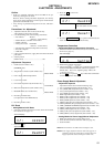
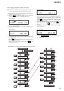
Adjustment Sequence
1. NV Reset (item number: 021)
(EEPROM clear)
r
2. Temperature Correction (item number: 015)
r
3. Power Supply Manual Adjustment
Manual Mode
r
4. Laser Power Check
r
5. CD Overall Adjustment (item number: 031)
r
Overall Mode
6.
MO
Overall Adjustment (item number: 034)
r
7. RESUME Clear (item number 043)
r
Manual Mode
8. Rewriting the Patch Data
(at replacement of the MAIN board)
r
9. Rewriting the NV values
0 21 ***SCC
Set LCD display
0 21 ResOK?
Set LCD display
Set LCD display
Res***
0
21
Reset!
0
21
NV reset (after several seconds)
0 15 SetTmp
Set LCD display