8
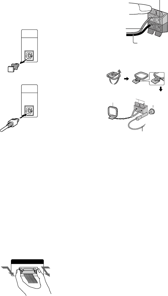
3 Connect the front speakers.
Connect the speaker cords to the FRONT
SPEAKER jacks.
4 Connect the FM/AM antennas.
Set up the AM loop antenna, then connect
it.
5 Connect the power cord to a wall outlet.
The demonstration appears in the display.
When you press ?/1, the system turns on
and the demonstration automatically ends.
If the supplied adaptor on the plug does not
fit your wall outlet, detach it from the plug
(only for models equipped with an adaptor).
FM75Ω/COAXIAL
AM
1 Connect the CD player and the tuner
with the optical cable.
Connect from the OPTICAL OUT jack on
the CD player to the OPTICAL IN jack on
the tuner.
1 Remove the cover of the jack.
2 Connect the optical cable.
2 Connect the flat system control cables
to the SYSTEM CONTROL connectors
until it clicks.
Connect to the same colored jack in the
order indicated on the rear panel.
A SYSTEM CONTROL 1 (Red)
Connect from the tuner to the A/V
amplifier.
B SYSTEM CONTROL 2 (Blue)
Connect from the tuner to the A/V
amplifier.
C SYSTEM CONTROL 3 (Black)
Connect from the CD player to the tuner.
D SYSTEM CONTROL 4 (Black)
Connect from the tuner to the cassette deck.
E SYSTEM CONTROL 5 (White)
Connect from the cassette deck to the CD
player.
Extend the FM lead
antenna horizontally.
AM loop antenna
SYSTEM CONTROL 3
FROM CDP-S3
To disconnect
Insert only the stripped portion.
–
R
L
+
OPTICAL
IN
FROM
CDP-S3
OPTICAL
IN
FROM
CDP-S3
Black/Stripe (#)
Red/Solid (3)
Hooking up the system (continued)


