– 70 –
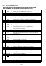
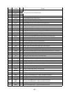
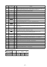
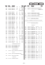
Pin No. Pin Name I/O Function
75 NC O
Not used (open)
76 BU-IN
I
Battery detect signal input from the SONY bus interface (IC600) and battery detect circuit
“L” is input at low voltage
77, 78 NC O
Not used (open)
79 KEYACK
I
Input of acknowledge signal for the key entry Acknowledge signal is input to accept function
and eject keys in the power off status On at input of “H”
80
TEL-ATT I
Telephone muting signal input terminal At input of “H”, the signal is attenuated by –20 dB
Used for the MDX-C5970/C5970R only (MDX-C5960R: fixed at “H”)
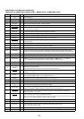
81 ST-MONO I/O
FM stereo broadcasting detection signal input from the FM/AM tuner unit (TU1), or forced
monaural control signal output to the FM/AM tuner unit (TU1)
“L” is input in the FM stereo mode, or “L” is output in the forced monaural mode
82 SEEKOUT O
Seek control signal output to the FM/AM tuner unit (TU1)
AM mode: Used for IF count output/SD output request/AGC cut at SEEK or BTM
FM mode: Used for SD speed up at SEEK, BTM, or AF
“L” is output at tuner off
83 SD-IN
I
Station detector detect input from the FM/AM tuner unit (TU1)
Stop level for SEEK, BTM, etc. is determined SD is present at input of “H”
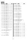
84 MONO O
Not used (open)
85 PLL CE O
PLL serial chip enable signal output terminal Not used (open)
86 HSTX I
Hardware standby input terminal “L”: hardware standby mode Reset signal input in this set
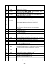
87 MD2 I
Setting terminal for the CPU operational mode (fixed at “L” in this set)
88 MD1 I
Setting terminal for the CPU operational mode (fixed at “H” in this set)
89 MD0 I
Setting terminal for the CPU operational mode (fixed at “H” in this set)
90 RESET I
System reset signal input from the reset signal generator (IC801) and reset switch (S900)
“L”: reset “L” is input for several 100 msec after power on, then it changes to “H”
91 VSS —
Ground terminal
92 X0
I Main system clock input terminal (3.68 MHz)
93 X1
O Main system clock output terminal (3.68 MHz)
94 VCC —
Power supply terminal (+5V)
95 POW-SEL
I
Power select switch input terminal “L”: off (halt mode), “H”: on (operation mode)
Not used (open)
96 POL MONO I
Polar monaural detection signal input terminal Not used (open)
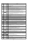
97 to 99 NC O
Not used (open)
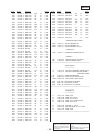
100
BAND
(9K-10K)
I
Frequency select switch (S701) input terminal
“L”: MW10k step/FM 200k step, “H”: MW 9k step/FM 50k step
Used for the E model only (Except E models: fixed at “H”)
101 NC O
Not used (open)
102 RAMBU I
Internal RAM reset detection signal input from the RN5VD23AA (IC802)
Input terminal to check that RAM data are not destroyed due to low voltage
This checking is made within 100 msec after reset
103 NC O
Not used (open)
104 LCD CE
O Chip enable signal output to the liquid crystal display driver (IC801) “H” active
105
FLASH-W
I
Internal flash memory data write mode detection signal input terminal “L”: data write mode
Not used (fixed at “H” in this set)
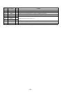
106 RE-IN0
I
107 RE-IN1
I
108
LAMP ON
(ILL ON)
O
Power on/off control signal output of the illumination LED and liquid crystal display driver
(IC801) “H”: power on
109 PW-ON
O Main system power supply on/off control signal output to the BA3918 (IC800) “H”: power on
110
FM-ON O
FM system power supply on/off control signal output to the BA3918 (IC800)
“L”: AM power on, “H”: FM power on
Dial pulse input of the rotary encoder (EN801)
(for VOLUME/BASS/TREBLE/BALANCE/FADER control)