


– 68 –
•
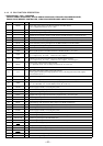
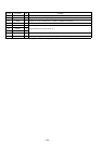
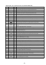
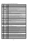
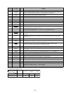
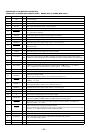
Pin No. Pin Name I/O Function
1 to 7 NC O
Not used (open)
8 VCC —
Power supply terminal (+5V)
9 PLL SI I
PLL serial data input terminal Not used (open)
10 PLL SO O
PLL serial data output terminal Not used (open)
11 PLL CKO O
PLL serial data transfer clock signal output terminal Not used (open)
12 NOSE-SW I
Front panel block remove/attach detection signal input terminal
“L”: front panel is attached
13 LCD SO
O Serial data output to the liquid crystal display driver (IC801)
14 LCD CKO
O Serial data transfer clock signal output to the liquid crystal display driver (IC801)
15
BEEP O Beep sound drive signal output terminal
16 DBMOD2 O
D-BASS mode control signal output terminal Not used (open)
17 DOOR-SW I
Front panel open/close detection signal input “L” is input when the front panel is closed
Not used (open)
18, 19 NC O
Not used (open)
20 UNI SI
I Serial data input from the SONY bus interface (IC600)
21 UNI SO
O Serial data output to the SONY bus interface (IC600)
22 UNI CKIO
I/O
Serial clock signal output to the MD mechanism controller (IC501) and SONY bus interface
(IC600) or serial clock signal input from the MD mechanism controller (IC501) (for SONY bus)
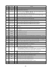
23 NC O
Not used (open)
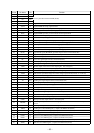
24
SIRCS
I
Sircs remote control signal input terminal Not used (fixed at “L”)
25 PACK-IND
O
LED drive signal output of the MD disc slot illumination and 6 indicator “H”: LED on
“H” is output to turn on LED when front panel is opened Not used (open)
26 VOL SO
O Serial data output for the electrical volume Not used (open)
27 VOL CKO
O Serial data transfer clock signal output for the electrical volume Not used (open)
28 DSTSEL0 I
Destination setting terminal
(Except German models: fixed at “H”, German model: fixed at “L”)
29 SYSRST O
System reset signal output to the MD mechanism controller (IC501) and SONY bus interface
(IC600) “L”: reset
30 DSTSEL1 I
Destination setting terminal
(US, Canadian models: fixed at “H”, E model: fixed at “L”)
31 DBMOD1 O
D-BASS mode control signal output terminal Not used (open)
32 TESTIN
I Setting terminal for the test mode “L”: test mode, Normally: fixed at “H”
33
VSS
—
Ground terminal
34 C —
Connected to coupling capacitor for the power supply
35 NS-MASK O
Discharge control signal output for the noise detection circuit “H”: discharge
Used for the MDX-C5960R/C5970R only (MDX-C5970: Not used (open))
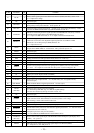
36 BUS- ON
O
Bus on/off control signal output to the MD mechanism controller (IC501) and SONY bus
interface (IC600) “L”: bus on
37 AD-ON
O
A/D converter power control signal output terminal
When the KEYACK (pin &ª) that controls reference voltage power for key A/D conversion input
is active, “L” is output from this terminal to enable the input
38 DVCC —
Power supply terminal (+5V) (for D/A converter)
39 DVSS —
Ground terminal (for D/A converter)
40 LCDANG
O
View field angle control signal is output when front panel is fully opened
“H”: front panel is fully opened
41 VOL CE
O Chip enable signal output for the electrical volume Not used (open)
42 AVCC
— Power supply terminal (+5V) (for A/D converter)
MAIN BOARD IC700 (MASTER CONTROLLER)
MB90574PFV-G-188-BND (MDX-C5960R/C5970R) MB90574PFV-G-187-BND (MDX-C5970)