


– 3 –
1. GENERAL
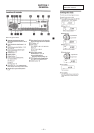
Location of controls ........................................................ 4
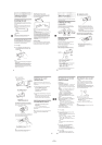
Resetting the unit ............................................................ 5
Detaching the front panel................................................ 5
Labelling the rotary commander..................................... 5
Using the rotary commander .......................................... 5
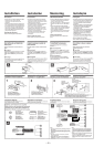
Adjusting the sound characterisitics ............................... 5
Attenuating the sound ..................................................... 5
Changing the sound and display settings ....................... 5
Boosting the bass sound.................................................. 5
Installation ....................................................................... 6
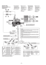
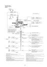
Connections ..................................................................... 7
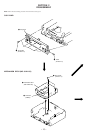
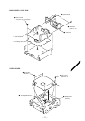
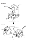
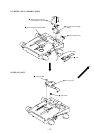
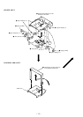
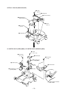
2. DISASSEMBLY ......................................................... 10
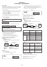
3. ELECTRICAL ADJUSTMENTS......................... 16
Test Mode ........................................................................ 16
MD Section ..................................................................... 16
Tuner Section .................................................................. 16
4. DIAGRAMS
4-1. Block Diagram – SERVO Section – ............................... 19
4-2. Block Diagram – TUNER Section – .............................. 21
4-3. Block Diagram – MAIN Section – ................................. 23
4-4. Block Diagram
– DISPLAY/KEY CONTROL Section –........................ 25
4-5. Block Diagram – BUS CONTROL/
POWER SUPPLY Section – ........................................... 27
4-6. Notes for Printed Wiring Boards and
Schematic Diagrams ....................................................... 29
4-7. Printed Wiring Board – SERVO Board – ....................... 31
4-8. Schematic Diagram – SERVO Board (1/3) – ................. 33
4-9. Schematic Diagram – SERVO Board (2/3) – ................. 35
4-10. Schematic Diagram – SERVO Board (3/3) – ................. 37
4-11. Printed Wiring Board
– MAIN Board (Component Side) – .............................. 39
4-12. Printed Wiring Board
– MAIN Board (Conductor Side) – ................................ 41
4-13. Schematic Diagram – MAIN Board (1/4) – ................... 43
4-14. Schematic Diagram – MAIN Board (2/4) – ................... 45
4-15. Schematic Diagram – MAIN Board (3/4) – ................... 47
4-16. Schematic Diagram – MAIN Board (4/4) – ................... 49
4-17. Printed Wiring Board – KEY Board –............................ 51
4-18. Schematic Diagram – KEY Board – .............................. 53
4-19. IC Pin Function Description ........................................... 62
5. EXPLODED VIEWS ................................................ 72
6. ELECTRICAL PARTS LIST ............................... 76
TABLE OF CONTENTS