


– 69 –
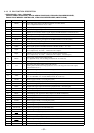
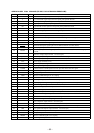
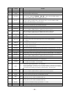
Pin No. Pin Name I/O Function
43 AVRH
I Reference voltage (+5V) input terminal (for A/D converter)
44 AVRL
I Reference voltage (0V) input terminal (for A/D converter)
45 AVSS
— Ground terminal (for A/D converter)
46 KEY-IN0
I
Key input terminal (A/D input) (LSW801 to LSW804, LSW806 to LSW810)
OFF, SOURCE, SEEK/AMS + ) + = 0 – , DSPL, SOUND, MODE, SHIFT, 1, 2
keys input (LSW804 DSPL: MDX-C5960R/C5970R only)
47 KEY-IN1
I
Key input terminal (A/D input) (LSW811 to LSW821)
6, AF/TA (MDX-C5960R/C5970R) DSPL (MDX-C5970), LIST PTY (MDX-C5960R/
C5970R) LIST (MDX-C5970), 10 to 3 keys input
48 KEY-IN2
I Key input terminal (A/D input) Not used (open)
49 RC-IN0
I Rotary remote commander key input terminal (A/D input)
50 D-BASS IN
I D-BASS switch (LSW805) input terminal (A/D input)
51 QUALITY
I
Noise level detection signal input at SEEK mode (A/D input)
Used for the MDX-C5960R/C5970R only (MDX-C5970: Not used (open))
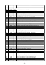
52 MPDH (MTP)
I
Multi-path detection signal input from the RDS decoder (IC102) (A/D input)
Used for the MDX-C5960R/C5970R only (MDX-C5970: Not used (open))
53
S-METER
(VSM)
I
FM and AM signal meter voltage detection input from the FM/AM tuner unit (TU1)
(A/D input)
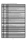
54 VCC —
Power supply terminal (+5V)
55 AMP ATT
O
Power amp muting on/off control signal output to the power amplifier (IC500)
“L”: muting on
56 AMP ON
O
Standby on/off control signal output to the power amplifier (IC500)
“L”: standby mode, “H”: amp on
57 ILL IN
I
Auto dimmer control illumination line detection signal input terminal
“L” is input at dimmer detection
58 LOCK IN
I Mini-disc lock detection signal input from the MD mechanism controller (IC501) “H”: lock
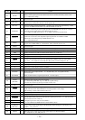
59 EMPH ON
O Emphasis control signal output terminal Not used (open)
60 AU ATT
O Audio line muting on/off control signal output terminal “H”: muting on
61 AF ATT
O Preamp muting on/off control signal output to the electrical volume (IC300) “H”: muting on
62 TU-ATT O
Muting on/off control signal output of the FM tuner signal “H”: muting on
Used for the MDX-C5960R/C5970R only (MDX-C5970: Not used (open))
63 VSS —
Ground terminal
64 ACC IN
I Accessory detect signal input terminal “L”: accessory on
65 AF-SEEK O
PLL low-pass filter time constant selection signal output at AF SEEK
“H” is output when AF SEEK Not used (open)
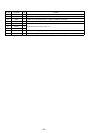
66
WIDE
O
67 DAVN I
Data transmit completed detect signal input from the RDS decoder (IC102) “H” active
Used for the MDX-C5960R/C5970R only (MDX-C5970: Not used (open))
68 NARROW O
Narrow select signal output terminal “H” active Not used (open)
69 SSTOP I
IF counter request signal input from the FM/AM PLL (IC100)
70 SDA I/O
Two-way data bus with the FM/AM PLL (IC100), RDS decoder (IC102) and electrical volume
(IC300) (RDS decoder is MDX-C5960R/C5970R only)
71 SCL O
Bus clock signal output to the FM/AM PLL (IC100), RDS decoder (IC102) and electrical volume
(IC300) (RDS decoder is MDX-C5960R/C5970R only)
72 RC-IN1
I Rotary remote commander shift key input terminal “L”: shift
73 X1A O
Sub system clock output terminal (32.768 kHz)
74 X0A I
Sub system clock input terminal (32.768 kHz)
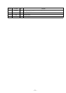
IF band select signal output terminal “H”: wide mode
In receiving FM signals, interference noise from adjacent stations is removed by narrowing the
IF band automatically in the tuner unit so as to raise the selectivity, but in this case, the distortion
may increase and accordingly, the IF band is widened forcibly Not used (open)