


Chapter 10
Setup Menus
Chapter 10
Setup Menus 10-23
Item number Item name
Settings
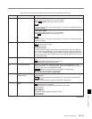
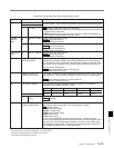
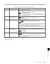
703 BLANK LINE SELECT Switch blanking on or off for individual lines in the vertical blanking interval of the
SD video signal. The Y/C signal and odd/even fields are blanked simultaneously.
Sub-Item
0 ALL LINE - - - : Specify the blanking for each line separately.
BLANK: Regardless of the setting of other sub-items, blank all lines which can be
specified in this menu item.
THROU: Regardless of the setting of other sub-items, switch off blanking for all
lines which can be specified in this menu item.
12 ...
20
LINE 12 ... LINE
20
In 59.94i,
29.97PsF
mode
Specify blanking for lines 12 to 20.
BLANK : Carry out blanking.
THROU: Switch off blanking.
In 50i, 25PsF
mode
9 ...
22
LINE 9 ... LINE 22 Specify blanking for lines 9 to 22.
BLANK : Carry out blanking.
THROU: Switch off blanking.
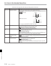
21 LINE 21 Specify blanking for lines 21.
BLANK : Carry out blanking.
HALF: Carry out half-blanking.
THROU: Switch off blanking.
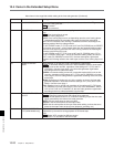
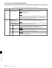
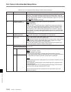
707
FORCED VERTICAL
INTERPOLATION OFF
The “Y-add”
a)
function is normally switched on automatically during jog or variable
speed playback. This item selects whether or not to force the “Y-add” function
off.
AUTO : Automatically switch the “Y-add” function on.
OFF: Force the “Y-add” function off.
709 CAV LEVEL FORMAT Select whether the analog component output should be D-1 or Betacam.
(Selectable only in 59.94i, 29.97PsF mode)
Sub-Item
OUTPUT CAV
LEVEL
0 Select the analog component output format.
B-CAM : Betacam
D1: D-1
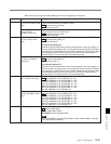
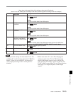
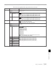
710 INTERNAL VIDEO
SIGNAL GENERATOR
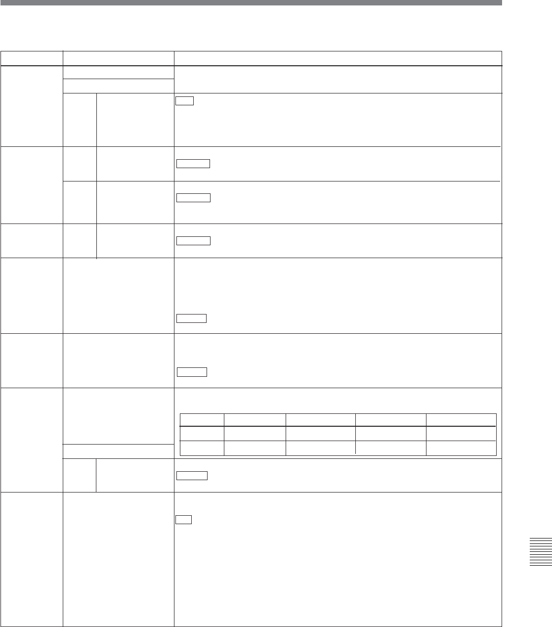
Format Color bars Y video Y sync R–Y/B–Y
D-1 CAV 100/0/100/0 700 mV 300 mV 700 mV
Betacam 100/7.5/77/7.5 714 mV 286 mV 700 mV
(Continued)
Select the test signal to be output from the VTR’s internal test signal generator.
OFF: No test signal is generated. (The VTR operates normally.)
CB : Color bar signal
MLTBS: Multi-burst signal
10STEP: 10-step signal
PLSBR: Pulse and bar signal
RAMP: Ramp signal
BLACK: Black signal
To turn on the internal test signal generator, hold the F1 (VID.IN) button in
function menu HOME page for three seconds or more with this menu item set to
other than OFF. When the test signal generator is turned on, the display of the
VID.IN setting changes to SG. To turn off the test signal generator, press the F1
(VID.IN) button in function menu HOME page again.
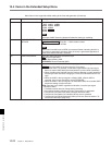
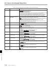
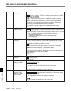
705 EDGE SUBCARRIER
REDUCER MODE
During recording and playback of a composite signal, in the playback circuit the
edge subcarrier reducer (ESR) is automatically switched on or off according to
the VTR operation. When recording a “Non-Standard” signal, for example, if the
color edges are not as good as with a proper signal, the ESR can be forced on.
This item makes this selection.
AUTO : ESR is switched on and off automatically.
ON: ESR operation is forced on.
Menu items in the range 700 to 799, relating to video control
a) The “Y-add” function is a circuit operation to interpolate
the video signal vertically during jog or variable speed
playback for the purpose of reducing the vertical
movement of the playback picture.