Powering the Amplifier
Power Cord Connection
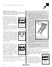
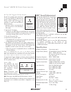
The ASAP3D SE features an IEC power
connector (see
Figure 3
). Plug the
female end of the power cord into the
Power Cord Connector on the amplifi-
er’s rear panel and plug the male end
into a grounded wall socket. Do NOT
plug the amplifier’s power cord into a
convenience outlet on any other audio
or video component. (Note: A power
cord is included only with the 120V
version of the amplifier.)
I
MPORTANT: DO NOT PLUG THE
POWER CORD INTO THE WALL OUTLET
UNTIL ALL SYSTEM CONNECTIONS HAVE BEEN MADE AND
VERIFIED.
N
OTE: IF YOU NEED TO USE AN EXTENSION CORD, USE ONLY A
HEAVY
-DUTY (16-GAUGE OR LARGER) EXTENSION CORD TO AVOID
STARVING THE AMPLIFIER OF ALL THE CURRENT NECESSARY FOR
FULL
-POWER OPERATION.
A.C. Fuse Holder
120V versions of the Sonamp ASAP3D
SE are shipped with a 2 amp AC fuse
installed. 230V versions have a 1.25
amp AC fuse installed. The fuse protects
the amplifier circuitry;
THE AC TRIGGER
OUTLET IS NOT PROTECTED BY THE FUSE.
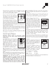
To replace the fuse, unplug the power
cord from the Power Cord Connector
and use a screwdriver to remove the
fuse holder (see
Figure 4
).
CAUTION: FOR CONTINUED PROTECTION AGAINST
FIRE, REPLACE THE FUSE WITH ONLY THE SAME TYPE AND
RATING.
SONAMP
®
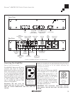
ASAP3D SE STEREO POWER AMPLIFIER
5
F
RONT
P
ANEL
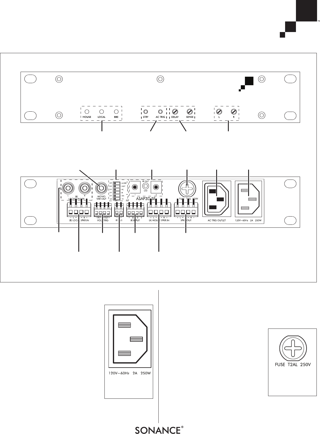
Status
LEDs
Local Source
Speaker-Level
Inputs
Voltage
Trigger
Connections
IR Bus
Connections
House
Speaker Input
Connections
IR Input
Connections
Speaker Output
Connections
Local Source
Line-Level
Inputs
Mono
Fixed/Variable
Output
Trigger and BBE
Mode Switches
IR Pass-Thru
Outputs
AC Fuse
Holder
Power Cord
Connection
AC
Trigger
Outlet
Standby and
AC Trigger
Pinhole Switches
R
EAR
P
ANEL
Input
Level Controls
Switching Delay and
Trigger Level Sense
Adjustments
FIGURE 2: ASAP3D SE FRONT AND REAR PANELS
FIGURE 3:
P
OWER CORD
C
ONNECTION
FIGURE 4:
A.C. F
USE
HOLDER


