


20
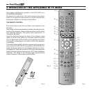
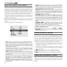
SELECTING THE AUDIO-VIDEO SOURCE
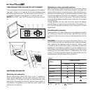
Having connected any external appliances to the RTX 55TV by
plugging in the relative cables, the socket to which each one
is connected must be selected via the OSD before the corre
-
sponding audio/visual signal can be reproduced. This is done
internally of a menu activated by pressing the AV button [10],
dedicated to selection of the sockets. Proceed as follows:
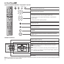
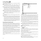
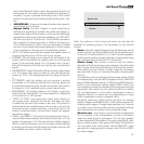
Press the AV button [10] to display the list of socket ports
available and select the code of the one to which the external
appliance is connected.
We can now look in detail at how to make a correct selection of
the socket from which the RTX 55TV picks up the audio-video
signal.
The menu displays the following options:
• “TV” displays the signal coming from the AERIAL SOCKET.
Note: If the intention is to connect a video recorder to this
socket, the audio-video signal must first be tuned and stored
before you can view it on the screen, as described in
“Tuning
and storing channels Manually”
.
In this instance, set number “0” as the “Programme” number
and number “36” (or whatever number is specified in the video
recorder handbook) as the “Channel”.
• “AV-1” displays the signal from the SCART 1 SOCKET; plug
the audio cables into the AUDIO L/R sockets serving this group
of connectors.
Note:
This socket can also receive an RGB video signal, and
accordingly, if the external appliance is one that supplies an
RGB signal to the socket, select the next option “AV-1 RGB”.
• “AV-2” displays the signal from the SCART 2 SOCKET; plug
the audio cables into the AUDIO L/R sockets serving this group
of connectors.
• “AV-3” displays the signal coming from the CINCH VIDEO
SOCKETS into which a cable with an RCA type connector
has been plugged. Plug the audio cables into the AUDIO L/R
sockets serving this group of connectors.
• “AV-3 Y/C” displays the signal coming from the SOCKET
into which a cable with a mini-DIN type connector has been
plugged. Plug the audio cables into the AUDIO L/R sockets
serving this group of connectors.
• “AV DVD” displays the components signal coming from
the three sockets Y, Cr and Cb, or the RGBs signal coming
from the four sockets G, R, B (which coincide with Y, Cr, Cb)
and Sync. Plug the audio cables into the AUDIO L/R sockets
serving this group of connectors.15 kHz inputs only are ac
-
cepted.
• “Graphic Mode” displays the signal coming from the
GRAPHIC INPUT socket. Plug the audio cables into the
AUDIO L/R sockets serving this group of connectors.
Making this selection, your RTX 55TV will be switched to
GRAPHIC MONITOR mode.
Certain adjustments can be made to the
“HI-FI”
and
“SUB-
WOOFER”
socket ports, which carry audio signals only; these
are described further on.
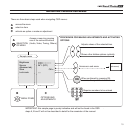
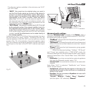
LOOPING TWO SOCKETS TOGETHER
The RTX 55TV can be used as an interfacing ‘bridge’ through
which to route an audio-video signal ENTERING the appliance
from an external appliance connected to one of the three soc-
kets listed below, and LEAVING by way of the Scart 2 socket
(labelled AV-2), to which another appliance is connected. The
connection between the two sockets is made as follows:
1) Press the AV button [10] to display the connections menu
and select the code for the socket to which the source
appliance is connected;
2) Press the blue button [3] to display the Other Functions
menu; select “Output AV-2” and then select one of the three
following options:
• “TV” if the signal comes from the AERIAL SOCKET.
• “AV-1” if the signal comes from the SCART 1 SOCKET.
•
“AV-3” if the signal comes from the CINCH VIDEO SOCKETS.
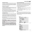
TUNING AND PROGRAMMING (TV MODE)
This section explains how to tune terrestrial channels received
via the aerial. You can tune and store channels in programme
numbers using one of two procedures: MANUAL or AUTO
-
MATIC.
AV-1-RGB
AV-1
AV
AV-2
AV-3
AV-3 YC
(SC1)
(SC1)
(RF)
(SC2) OK
(CVBS)
(SVHS)