


E-4
System connections (continued)
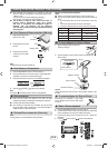
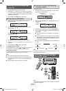
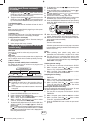
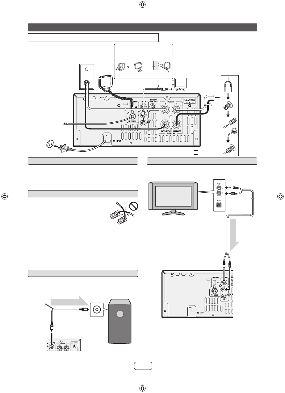
Speaker connection
For XL-HF201P(BK)
Connect the black wire to the minus (–) terminal,
and the red wire to the plus (+) terminal.
For XL-HF301P(T)
Connect the wire without insulation tube to the
minus (–) terminal, and the wire with red insulation
tube to the plus (+) terminal.
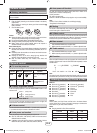
Use speakers with an impedance of 4 ohms or
more, as lower impedance speakers can damage the unit.
Do not mistake the right and the left channels. The right speaker is the
one on the right side when you face the unit.
Do not let the bare speaker wires touch each other.
Do not allow any objects to fall into or to be placed in the bass refl ex
ducts.
Do not stand or sit on the speakers. You may be injured.
Volume control
The sound level at a given volume setting depends on speaker effi ciency,
location and various other factors. It is advisable to avoid exposure to high
volume levels, which occurs while turning the unit on with the volume control
setting up high, or while continually listening at high volumes. Excessive sound
pressure from earphones and headphones can cause hearing loss.
Incorrect
Make sure to unplug the AC power cord before making any connections.
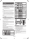
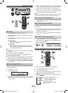
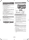
Subwoofer pre-out connection
You can connect a subwoofer with an amplifi er to the SUBWOOFER PRE
OUT jack.
Commercially available subwoofer
(amplifi er built in)
Audio cable
(commercially
available)
Audio signal
To audio
input jack
To SUBWOOFER
PRE OUT jack
Main unit
Notes:
No sound is heard from the subwoofer without a built-in amplifi er.
Subwoofer Pre-out (audio signal): 200mV / 10k ohms at 70 Hz.
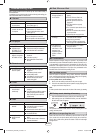
Line input connection (TV, etc.)
Connect to the TV using an audio cable.
TV
To audio
output jack
Audio cable
(commercially
available)
Audio signal
To LINE input
jack
Main unit
To select Line In function:
On main unit: Press FUNCTION button repeatedly until Line In is
displayed.
On remote control: Press AUDIO/LINE (INPUT) button repeatedly until
Line In is displayed.
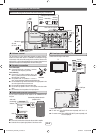
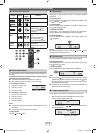
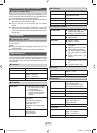
AC outlet
(AC 120 V ~ 60 Hz)
FM antenna
Right
speaker
Video cable (not supplied)
To video input jack
Left
speaker
Red
Black
Installing the AM loop antenna
< Assembling >
< Attaching
to the wall >
Wall
screws (not supplied)
AM loop
antenna
XL-HF201P_HF301P_US.indd 4XL-HF201P_HF301P_US.indd 4 3/7/2012 10:35:20 AM3/7/2012 10:35:20 AM