48
8 Putting the EM 3532 into operation
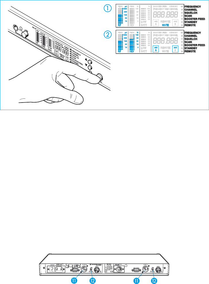
The receivers are switched on separately with the ON / OFF switches ². The respective display
panel » is now lit up to show that the receiver is switched on, and the standard display is shown
(see chapter 11). The display “
MUTE” ቢ (see chapter 15) lights up, and the RF field strength is
indicated. If a suitable transmitter is already operating on this frequency, the display “MUTE” is
initially lit up for about two seconds. Then the deviation is indicated ባ (modulation, see chapter
21), and the diversity branch in use is now displayed for the first time (see chapter 4).
After approx. ten more seconds, the battery status display indicates the (remaining) capacity of the
transmitter’s battery or rechargeable accupack, provided the transmitter in use transmits a battery
status signal (see chapter 24).
Note
The ON / OFF switch ² works in the secondary circuit of the integrated mains
transformer, and thus only switches the low voltage side. By using a modern magnetic
core transformer, the power consumption of a receiver of approx.
1
/
2
Watt when
switched off is extremely low. For larger installations with several receivers, a
complete mains disconnection can best be achieved by an additional common
ON / OFF switch.
The AF connection is via sockets
¸ on the rear. The controls ¹ control the AF signal output
level.


