


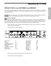
SETTING UP THE S•3-way
Whether you are an experienced audio engineer or just starting out, the next sections of this manual will help you
get going with your S•3-way. Now that you have unpacked the unit and have become a bit familiar with the front
panel controls, you can follow the next sections of this manual to begin to set-up and operate your new
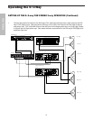
crossover.Further on in this manual, you will find detailed wiring diagrams of various speaker system set-ups.
For detailed diagrams of connector and cable wiring, see page 15 in this manual.
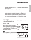
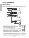
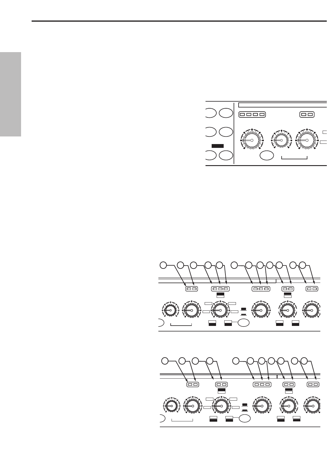
MODE SWITCH
The S•3-way can be configured to operate in several modes
including Stereo or Mono 2-way, Stereo or Mono 3-way and
Mono 4-way. In addition, the S•3-way has a special operating
mode; 4-way LOW which is used for ultra-low sub woofer appli-
cations. The Mode Switch, located in the center section of the
unit, is used to select the operating mode. As you switch through
the various operation modes, you will notice that several LED’s
on the panel are also changing. These are the Mode Indicator
LED’s and they help you keep track of the changing controls.
INPUT GAIN DELAY GAIN
HPF
50
0
5
9
5
dB
-12 +12
+6-6
0
dB
-6 +6
0
mSec
02
1
-20 -10
LIMLOW
+100
HIGH
LOW
MID
H MID
H MID
P
HASE MUTE
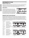
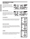
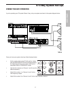
FREQUENCY BAND & LIMIT INDICATORS
Because the S•3-way can be configured to operate in several different size sound systems, the crossover con-
trols may be adjusted for the frequency division between low, and high, or low and low-mid, or high mid to high
depending on the mode. On some crossovers, it is very difficult to get a quick visualization as to what controls are
controlling what function. The S•3-Way solves this problem by employing it’s Mode Indicator LED’s over the
Frequency and Gain controls. These provide quick identification of the frequency band that is under control. In
the diagrams below, you can see what functions are under control when the associated LED is lit. Also, over each
Gain control is an LED that illuminates indicating that frequency band has entered into Limiting. More information
on using the Limiter can be found on page 10.
1
2
4 5
3
7 86 12 11 10 9
DELAY GAIN GAIN
P
F
Hz
FREQ
1.5K
75
150
8K
800
400
350
35
18
5K
500
500
50
2.6K
260
950
95
35-800
RANGE
6
dB
-6 +6
0
dB
-6 +6
0
2
1
LIMLOW L/LML/ML/H LIMLMIDMID
350-8K
mSec
0
GAIN
Hz
FREQ
1.5K
750
1.5K
8K
4K
8K
350
175
350
5K500
2.6K950
dB
-6 +6
0
LM/HMM/H
LIMHIGH
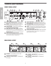
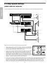
CHANNEL 1
Operating the S•3-way
Channel One
1 LOW Low Frequency Gain
2 LIM Low Band Limiter
3 L/H Crossover Low to High
4 L/M Crossover Low to Mid
5 L/LM Crossover Low to Low-Mid
6 MID Mid Frequency Gain
7 LMID Low-Mid Gain
8 LIM Mid/Low-Mid Band Limiter
9 M/H Crossover Mid to High
10 LM/HM Crossover Low-Mid to High-Mid
11 HIGH High Frequency Gain
12 LIM High Band Limiter
13
14
16
15
18 1917 232221 20
GAIN GAIN
Hz
FREQ
2.6K
2.6K
1.5K
8K
8K
8K
350
700
350
5K500
2.6K950
dB
-6 +6
0
dB
-6 +6
0
MID LIMHMID HM/HM/H LIMHIGH
DELAY GAIN
P
F
Hz
FREQ
1.5K
150
1.5K
8K
800
8K
350
35
5K
500
500
50
2.6K
260
950
95
35-800
350-8K
RANGE
dB
-6 +6
0
mSec
02
1
L/ML/HLIMLOW
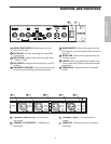
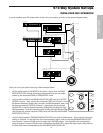
CHANNEL 2
350
Channel Two
13 LOW Low Frequency Gain
14 LIM Low Band Limiter
15 L/H Crossover Low to High
16 L/M Crossover Low to Mid
17 MID Mid Frequency Gain
18 HMID High-Mid Gain
19 LIM Mid/High-Mid Band Limiter
20 M/H Crossover Mid to High
21 HM/H Crossover High-Mid to High
22 HIGH High Frequency Gain
23 LIM High Band Limiter
6
ENGLISH