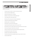
4
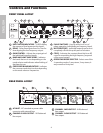
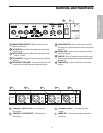
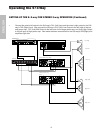
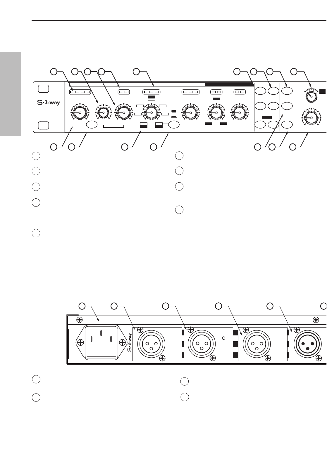
C CHANNEL 2 MID OUTPUT - XLR balanced
line output.
D CHANNEL 2 LOW OUTPUT - XLR balanced
line output.
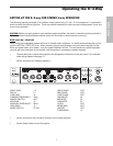
1 INPUT METER INDICATORS - 4 LEDS display
the amount of level present at the inputs.
2 DELAY - Delay line adjusts from 0 to 2ms for
time aligning the low frequency output.
3 GAIN CONTROL - Adjusts the output gain of
the individual frequency bands.
4 BAND AND LIMIT INDICATORS - Indicates
the bands that are in use depending on the
mode selector and indicates when limiting of
that band occurs.
5 CROSSOVER BAND INDICATORS - Indicates
the crossover mode that is active depending
on the mode selector frequencies.
INPUT GAIN DELAY GAIN GAIN
HPF
Hz
FREQ
1.5K
75
150
8K
800
400
350
35
18
5K
500
500
50
2.6K
260
950
95
35-800
RANGE
-12
+6-6
0
dB
-6 +6
0
dB
-6 +6
0
2
1
-20 -10
LIMLOW
+100
L/LML/ML/H LIMLMIDMID
350-8K
dB
+12
mSec
0
GAIN
Hz
FREQ
750
1.5K
4K
8K
175
350
5K500
2.6K950
dB
-6 +6
0
LM/HMM/H
LIMHIGH
CHANNEL 1
HIGH
LOW
MID
L MID
L MID
PHASE MUTE
LIMITER
CD EQ
MONO
SUB
THRESHOLD
dB
+18
-5
+14
-2
+10
0
MONO
4 W
ST
3 W
4 W
LOW
ST
2 W
+5
STEREO/MONO
CROSSOVER
12
13
14 15
16
17
18
1
3
4
8
2
9765
6 PHASE SWITCHES - Used to select in or out of
phase operation, individually per frequency band.
7 MUTE SWITCHES - Individual outputs can be shut
completely off with the quick press of a button.
8 CD EQ - Activates the constant directivity horn EQ
curve for smoothing the high frequency response
of the sound system.
9 OPERATING MODE SELECTOR - Selects one of the
4 operating modes; 2-way stereo, 3-way stereo, 4-
way mono and 4-way low.
A AC INLET - IEC standard ac power cable
connector with external fuse.
B CHANNEL 2 HIGH OUTPUT - XLR balanced
line output.
CH 2
HIGH
OUTPUT
MONO
HIGH
OUTPUT
CH 2
MID
OUTPUT
MONO
HIGH-MID
OUTPUT
CH 2
HIGH
OUTPUT
CH 2
LOW
OUTPUT
CH 2
LOW
OUTPUT
I
I
A CB
D
E
F
Controls and Functions
REAR PANEL LAYOUT
FRONT PANEL LAYOUT
ENGLISH


