12
+
+
ST2 Tuner Side View
Rack Ear
Front View
Rack Ear
Side View
Rack Ear
Screw Holes
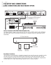
Rack Mount Installation
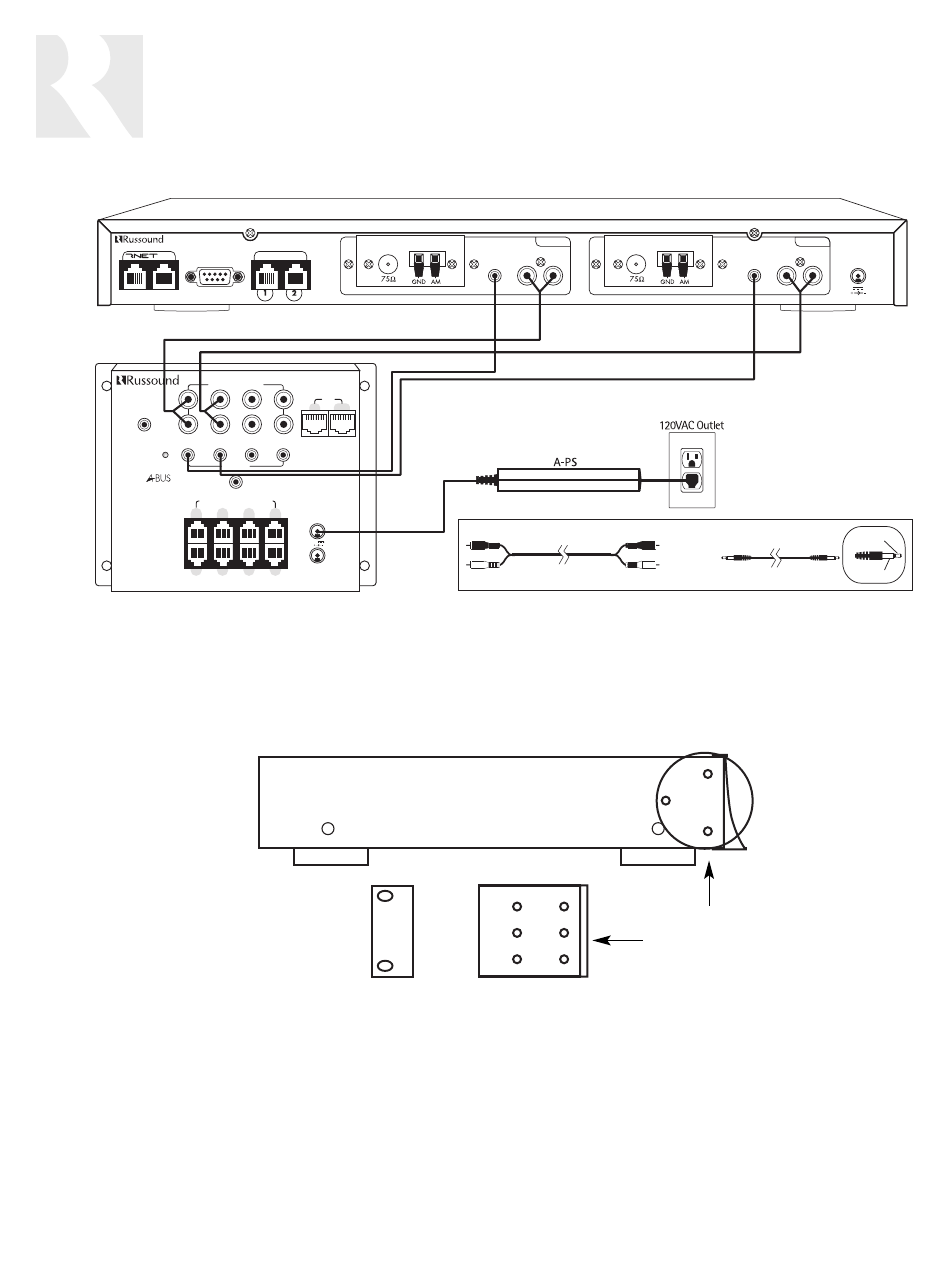
The ST2 tuner can be mounted in a standard component rack using the rack ears provided. Line the
rack ear’s two rows of screw holes with the three screw holes on the side of the tuner. Use the
screws provided to secure the rack ears onto the unit on both sides. The ST2 Tuner should not be
installed adjacent to a high heat-producing component such as a power amplifier.
R
L
SERIAL#
DESIGNED IN USA MADE IN KOREA
4321
SOURCE IR
C
OMMON IR
OUTPUT TO
B KEYPADS
OUTPUT TO
A KEYPADS
TRIGGER OUT
12
VDC
100mA
SYSTEM ON
A/B COUPLED-ZONE OUTPUT
SOURCE AUDIO INPUT
N
EWMARKET
, NH U.S.A.
A-H484
P
OWER FOR
A KEYPADS
P
OWER FOR
B KEYPADS
4A
+24V
3
A
1
A
2
A
4
A
3
B
1
B
2
B
4
B
LINK
OUT
IN
4 COUPLED-ZONE, 4-SOURCE
PANEL MOUNT AUDIO HUB
RS-232
INTERFACE
IR
LR
A
UDIO OUTPUT
12VDC 1.5A
I
N OUT
NEWMARKET, NH U.S.A.
ST2
Smart Tuner
LINK KEYPAD PORTS
TUNER 1TUNER 2
FM COAX
LOOP
ANTENNA
FM COAX
LOOP
ANTENNA
Serial#
MADE IN KOREA
IR
LR
A
UDIO OUTPUT
Pos (+)
Neg (–)
RCA Cable
RCA Cable
RCA Cable
IR Link Cable
IR Link Cable
IR Link Cable
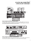
Source Connections with A-BUS Audio Distribution Hub
The diagram depicts a typical setup using the ST2 Tuner with an A-BUS system’s audio distribution
hub. Each tuner in the ST2 unit must be connected as a separate source for audio inputs and IR
connections.
ST2 SETUP AND CONNECTIONS
A-BUS CONNECTIONS AND RACK MOUNT OPTION


