5.3X INSTALLATION
I
N
S
T
A
L
L
A
T
I
O
N
® ®
– 24 –
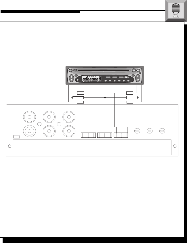
High Level Input – “Single Ended” Type
This configuration is used for source units that have “Single Ended” speaker
outputs. Only the “+” output is “hot,” whereas the “–” or “common” are
common grounded. To verify your source unit has these outputs, connect an
ohm meter across the “–” output and radio chassis for a reading of 0Ω.
• L+ and R+ Inputs are connected to corresponding “+” speaker outputs
• L– and R– Inputs are
not used
• GND Input is connected to “–” speaker outputs
• Configuration #6* is used with FRONT inputs to achieve Sub output
• Configuration #3* is used with FRONT & REAR inputs to achieve Sub output
* Refer to previous pages for
Signal Switching Network
configurations
CAUTION: Use 1/8" female connectors when using the high level inputs and DO NOT
solder wires directly to the connector
Front
Gain
LED
Rear
Gain
Sub
Gain
High Level Inputs
+LF–
+RF–
+LR– +RR–GND
LR
RR
L-Subwoofer
R-Subwoofer
LF
RF
Front
Rear
R+
COMM
Use “Configuration #6” of
Signal Switching Network
when using front inputs only
Use “Configuration #3” of Signal
Switching Network when using
front & rear inputs
COMM
L+ R+
L+
AUD
SEL
1 2 3 4 5 6
RDM
RPT
SCAN
PAUSE
D.SCN
DIM
AM
FM
Ch
RPTLD
RDM
DISC
ST
P.SCN LOUDDSPL
R
CLOCK
ILLUM
PWR
AUTO
® ®
VOL
TUNE


