


– 10 –
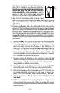
Trim the power cable within 18" of the battery and
strip 1/2" of insulation from the end of the wire.
Cut the wire loop that is attached to the fuseholder
in half and splice the fuse into the power line
using appropriate inline connectors. Use the
section of cable that was trimmed earlier and
connect it to the other end of the fuseholder.
4. Strip 1/2" from the battery end of the power cable
and crimp a large ring terminal to the cable. Use the ring terminal
to connect to the battery positive terminal. Do not install the fuse
at this time.
5. Prepare the Ground cable for attachment to the amplifier by
stripping 1/2" of insulation from the end of the wire. Insert the bared
wire into the GND terminal and tighten the set screw to secure the
cable in place. Prepare the chassis ground by scraping any paint
from the metal surface and thoroughly clean the area of all dirt and
grease. Strip the other end of the wire and attach a ring connector.
Fasten the cable to the chassis using a non-anodized screw and a
star washer.
6. Prepare the REM turn-on wire for connection to the amplifier by
stripping 1/2" of insulation from the wire end. Insert the bared
wire into the REM terminal and tighten the set screw to secure the
cable into place. Connect the other end of the REM wire to a
switched 12 volt positive source. The switched voltage is usually
taken from the source unit's auto antenna or the accessory lead.
If the source unit does not have these outputs available, the
recommended solution is to wire a mechanical switch in line with
a 12 volt source to activate the amplifier.
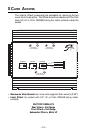
7. Securely mount the amplifier to the vehicle or amp rack. Be
careful not to mount the amplifier on cardboard or plastic panels.
Doing so may enable the screws to pull out from the panel due to
road vibration or sudden vehicle stops.
8. Connect the source signal to the amplifier by plugging the RCA
cables/high level inputs into the input jacks at the amplifier.
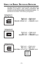
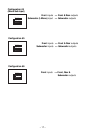
9. Connect the speakers. Strip the speaker wires 1/2" and insert into
the speaker terminal and tighten the set screw to secure into
place. Be sure to maintain proper speaker polarity.
DO NOT
chassis ground any of the speaker leads as unstable operation
may result.
10. Perform a final check of the completed system wiring to ensure
that all connections are accurate. Check all power and ground
connections for frayed wires and loose connections which could
cause problems.
Cut
here
X