


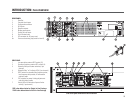
FEATURES & SETUP- REAR PANEL SWITCHES: MODE
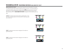
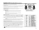
MODE-
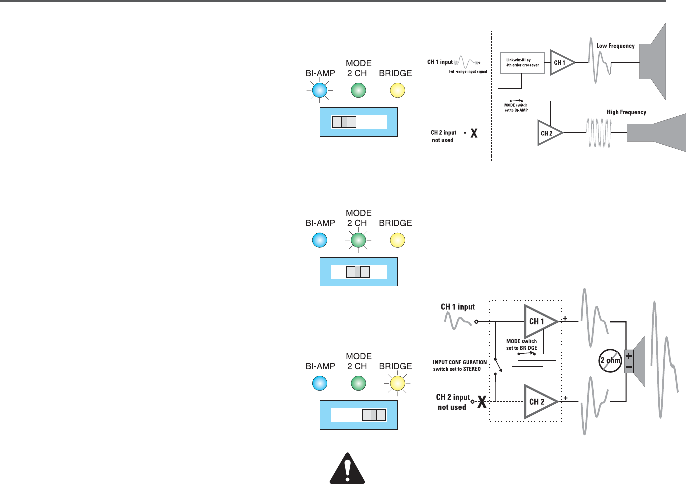
This switch selects between BI-AMP, 2 CH, or BRIDGE modes of operation.
The indicator LED’s above the switch confirm the selection.
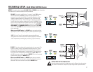
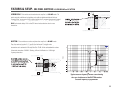
BRIDGE: This mode combines both output channels into one output. This
mode is for driving a single, high-powered load with twice the “normal”
voltage swing. This results in about 4 times the peak power and about
three times the sustained power of a single channel. This mode uses the
input, gain control, subaudio filter, and clip limiter of CH 1; CH 2's filter
and clip limiter have no effect. The yellow BRIDGE
LED on the front panel
indicates when the amp is in BRIDGE mode.
When to use BRIDGE mode: Use BRIDGE mode when you need to
deliver the power of two channels to a single 8 or 4 ohm load, such as a
subwoofer. Do not use less than 4 ohm loads in BRIDGE mode.
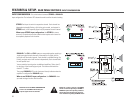
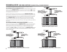
2 CH: This is the “normal” mode used for stereo and parallel input
configuration. Each channel carries full-frequency signals (no crossover)
and is independently controlled (gain, processing, output connection).
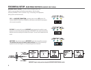
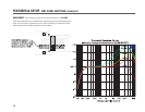
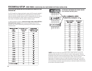
BI-AMP: This puts the amplifier into a “crossover” mode. CH 1 receives
the low frequencies and CH 2 is receives the high frequencies. The
crossover is a 4
th
order Linkwitz-Riley. The crossover frequency and low-
frequency alignment delay are “programmed” with SIP (single in-line
package) resistor networks . These small plug-in networks are installed
from the side of the amplifier and plug into J4 and J5. WARNING: Do not
insert or remove networks with the power turned on. See the SIP Network
Selection and Installation section for more information. The HF ATTEN,
HORN BOOST, and SUBAUDIO FILTER controls are active in BI-AMP
mode. The blue BI-AMP
LED on the front panel indicates when the amp
is in bi-amp mode.
When to use BI-AMP mode: Use BI-AMP when you need to split the
high frequency and low frequency signals to power separate driver types.
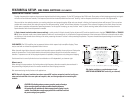
BRIDGE MODE OUTPUT CONNECTION-
Note that speaker connection for bridge mono mode is different than other modes.
See section on Connections: Outputs for proper bridge mode output connections.
7