


FEATURES & SETUP- SIDE PANEL: CROSSOVER & DELAY NETWORK SELECTION & INSTALLATION
SIP RESISTOR NETWORK INSTALLATION GUIDELINES AND SELECTION
INFORMATION
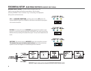
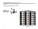
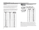
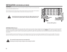
Your PL2A amplifier is shipped configured to order with SIP networks installed. If
the factory set up is not applicable for your application,then you will need to
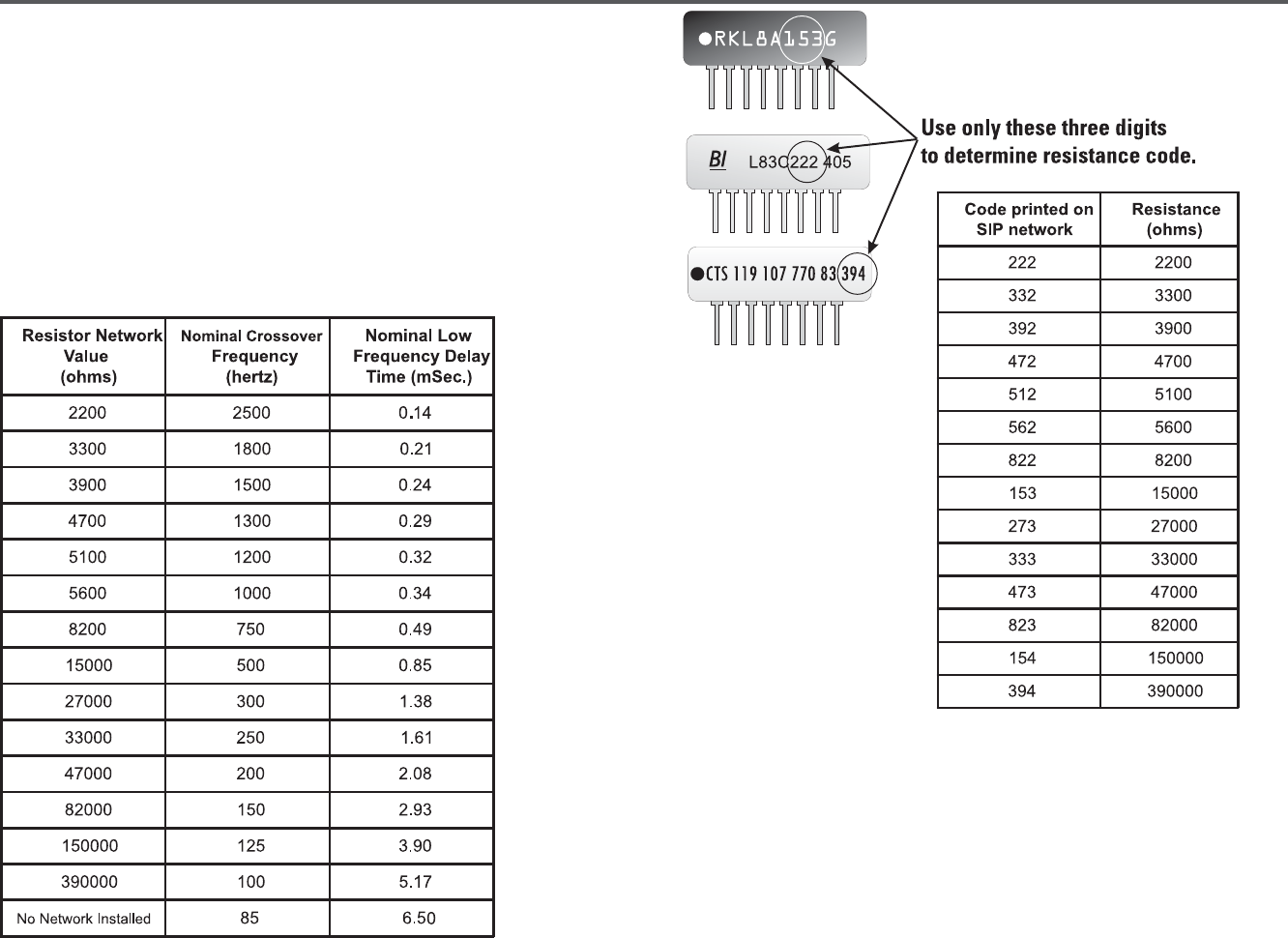
know your desired crossover frequency and low frequency delay time in order to
select the corresponding SIP resistor network values. Refer to the selection
chart, below, for nominal crossover frequency and delay values.
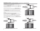
A general guideline would be to
never use a larger value of delay SIP than
that used for the crossover
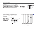
. After choosing the desired values from the
selection chart, locate the plastic bag containing the SIP networks and locate
the desired value.
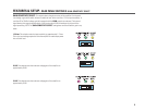
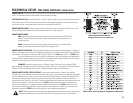
DECODING SIP NETWORK RESISTANCE VALUES
(see note below decoding chart)
NOTE: Due to the number of manufacturers of SIP resistor networks, we can not
possibly provide examples of all the various part number marking schemes. We have
provided the three most common marking schemes, above. If the SIP networks you have
received do not conform to one of the above schemes, QSC’s Technical Services
Department will be glad to assist you in determining the resistance value of your SIPs.
Alternatively, you could measure the resistance value with a multimeter; simply set you
meter to the proper resistance range and connect your multimeter’s leads to the first two
pins of either end to obtain the value.
16