


TECHNICAL OVERVIEW: BLOCK DIAGRAM & OPERATIONAL DETAILS
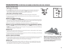
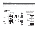
High Performance Audio. High speed power transistors convert this DC power into the full range audio output which drives the speakers. High-current design and special dual-sense
output feedback corrects errors on both sides of the speaker terminals, improving damping and control of speaker motion. The power devices are directly mounted to isolated heat sinks,
which form a short, wide air tunnel in front of the fan for optimum cooling.
Each channel has a thermal sensor embedded in its heat sink for accurate temperature monitoring. The sensor controls fan speed, bias tracking and thermal shutdown. It also reports
temperature readings to the DataPort (for remote monitoring with QSC's CM16a Processor).
The output circuitry is actively clamped during clipping for smooth and very fast recovery. The clamp also feeds a proportional clip limiter, which actually senses the depth of clipping and
responds accordingly.
The balanced inputs use premium 0.1% precision resistors for very high noise rejection. The precision components used in the input filters and all other circuitry ensure accurate
performance.
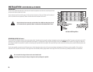
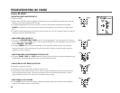
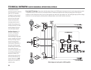
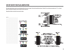
Basic functional block diagram
of PowerLight™ power supply
Shutdown. The amplifier mutes as soon as power is
shut off, preventing turn-off noises. Serious faults
trigger a shutdown of the power supply; the high
switching frequency allows the power supply to shut
down within microseconds to limit damage.
29
EMI Filter
Inrush Limiting
Main Energy Bank
PowerLight Switching
DC Supply for
Amplifier
Transformer
Control
Power
PLM
Control