


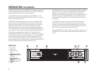
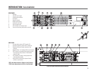
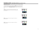
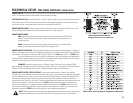
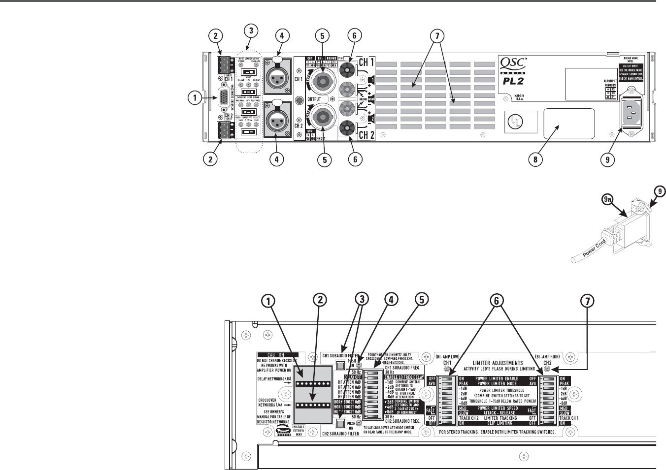
REAR PANEL
1. DataPort
2. Terminal block inputs
3. Configuration switches
4. XLR inputs
5. Speakon outputs
6. Binding post outputs
7. Cooling air inlet vents
8. Serial number label
9. IEC connector for AC power cord
9a. Power cord retaining clip (install on item 8)
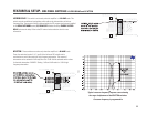
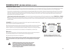
SIDE PANEL
1. Low pass delay network SIP* socket (J5)
2. Crossover frequency network SIP socket (J4)
3. Subaudio filter push-button switches (1 per
channel)
4. Subaudio filter “on” indicator LEDs (1 per channel)
5. DIP** switch for subaudio filter frequency select,
low frequency delay enable, HF attenuation
and horn boost
6. DIP switches for power limiting adjustments
and clip limiting enable
7. Activity LEDs for indication of power limiter
activity (1 per channel)
*SIP is the abbreviation for Single-In-line Package
**DIP is the abbreviation for Dual-In-line Package
INTRODUCTION: PL2A OVERVIEW
5
Side cover plate removed for this illustration