


Tsunami MP.11 Antenna Installation
Copyright © 2006 Proxim Wireless Corporation. All rights reserved. 30
Notes:
• The RSL must be higher than the Receiver Sensitivity plus the fade margin for a good link. See Table 1 to
have a working link with no excessive errors. The amount of Fade Margin indicates the reliability of the link;
the more Fade Margin, the more reliable the link.
• The path loss must be smaller than the link budget minus the minimum required fade margin. The maximum
ranges cause the path loss plus the fade margin to be the same as the link budget.
The results of this link budget calculation are very important for determining any potential problems during
installation. If you have calculated the expected RSL, you can verify that it has been achieved during installation
and troubleshooting, if necessary.
In the USA and Canada, this model radio can be installed with any gain directional antennas, as there is no
Effective Isotropic Radiated Power (EIRP) limit for the application of these systems for fixed point-to-point
applications in the 5.8 GHz frequency band. In other bands and in other countries, EIRP limits may apply.
In the case of EIRP limits, use the lesser of either (P
out
- L
1
+ G
1
) or the EIRP limit within the previous equation.
You should check this equation in both directions to assure legal application. An EIRP limit is the maximum RF
energy that can be transmitted, as measured at the transmitting antenna, and is usually determined by
government regulations.
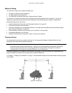
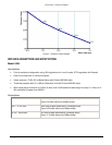
Proxim’s recommendation is to keep at least 60-70% of the first Fresnel zone free. If the clearance is lower than
this percentage, the link budget and achieved fade margin are affected. Clearances more than 100% of the
Fresnel zone can cause reflections that are 180 degrees out of phase and can cancel out the signal. The Fresnel
zone works in both the horizontal and vertical paths.
The first Fresnel zone size is a list; Proxim’s recommendation is to keep at least 60-70% of this zone free. If the
clearance is lower than this percentage, the link budget and achieved fade margin are affected. Clearances more
than 100% of the Fresnel zone can cause reflections that are 180 degrees out of phase and can cancel out the
signal. The Fresnel zone works in both the horizontal and vertical paths.
Tables for output levels can be found in the Technical Specifications in the Tsunami MP.11 Installation and
Management manual.
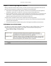
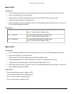
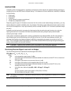
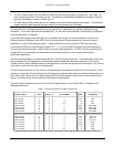
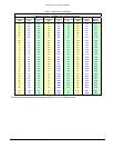
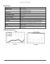
Table 1. Examples of Minimum Antenna Cable Loss
Frequency Band
Antenna
Gain
TPC
Setting
Minimum Cable Loss for Data
up to 24 Mbps*
EIRP
Deployment
5.25-5.35 GHz
5.25-5.35 GHz
5.25-5.35 GHz
5.25-5.35 GHz
5.725-5.85 GHz
5.725-5.85 GHz
5.725-5.85 GHz
5.725-5.85 GHz
10
17
23
31
10
17
23
31
0
-6
-10
-10
0
0
-6
-10
0
0
1.5
9.5
0
0
0
3.5
28.5
29.5
30
30
28.5
35.5
35.5
36
USA
USA
USA
USA
USA, PtMP
USA, PtMP
USA, PtMP
USA, PtMP
5.725-5.85 GHz
5.725-5.85 GHz
5.725-5.85 GHz
5.725-5.85 GHz
5.47-5.725 GHz
5.47-5.725 GHz
5.47-5.725 GHz
5.47-5.725 GHz
10
17
23
31
10
17
23
31
0
0
0
0
0
-6
-10
-10
0
0
0
0
0
0
1.5
9.5
28.5
35.5
41.5
49.5
28.5
29.5
30
30
USA, PtP
USA, PtP
USA, PtP
USA, PtP
ETSI
ETSI
ETSI
ETSI
* Note that higher data rates use lower output power, so less cable loss is required to meet the maximum EIRP limit.