


Tsunami MP.11 Antenna Installation
Copyright © 2006 Proxim Wireless Corporation. All rights reserved. 28
CALCULATIONS
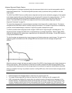
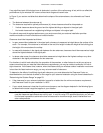
Availability of the microwave path is a prediction of the percent of time that the link operates without producing an
excessive bit error rate (BER) due to multipath fading. In the absence of direct interference, availability is affected
by the following:
• Path length
• Fade margin
• Frequency
• Terrain (smooth, average, mountainous)
• Climate (dry, temperate, humid)
Depending upon the type of information carried over the link and the overall network design redundancy, you may
want to design for a specific availability rate. For example, if the data or voice traffic carried by the radio is critical,
the link can be designed for a very high availability rate (for example, 99.999% or 5.3 minutes of predicted outage
per year).
Availability can be improved by increasing the fade margin either by making the path shorter or by using the
higher gain antennas in conjunction with lower loss antenna cable (using a higher quality antenna cable,
shortening the length, or both).
If the system is intended to operate with “roaming” of Subscriber Units between BSUs, the SU must maintain a
high enough signal level while switching from one BSU to the next. Due to the time necessary to switch, the
coverage (and therefore the distance between the BSUs) is impacted by the speed of movement of the SU or
RSU. The Link Budget of both links between an SU or RSU and either BSU must be high enough to allow good
quality communication and a smooth handover.
Note: In previous 1.x versions of the software in which the SU had a long timeout upon registration, the switch to
a new BSU is made only when the link with the current BSU is lost for at least 30 seconds).
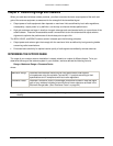
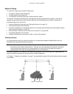
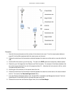
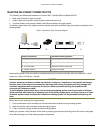
Calculating Received Signal Level and Link Budget
Use the following formula to estimate the received signal level (RSL):
RSL (dBm) = P
out
- L
1
+ G
1
+ G
2
- L
2
- L
p
where:
P
out
is the transmitter output power (in dBm)
L
1
is the total loss of all transmission elements between the antenna and the RF Unit on one side of
the link (in dB)
G
1
is the gain of the antenna on one side of the link (in dB)
G
2
is the gain of the antenna on the opposite side of the link (in dB)
L
2
is the total loss of all transmission elements between the antenna and the RF Unit on the
opposite side of the link (in dB)
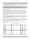
L
p
is the Path loss, defined by:Lp (dB) = 96.6 + 20 log
10
F + 20 log
10
D
where:
F is the Frequency of the radio system in GHz (5.8 or 2.4 GHz)
D is the Distance of the path in miles
Note: This formula is available on a calculation sheet provided by Proxim to generate an estimate of link distance
and reliability.
See the following figure for a visual representation of the elements of this equation.