Tsunami MP.11 Antenna Installation
Copyright © 2006 Proxim Wireless Corporation. All rights reserved. 16
To minimize the influence of obstacles, signal interference, or reflections, note the following guidelines:
• Mount the antenna as high as possible above the ground to allow maximum clearance:
º In open areas, ground is the actual surface of the earth.
º In dense urban areas, ground is to be interpreted as the height of the highest obstacle in the signal path
between the two antenna sites.
• Avoid trees in the signal path to avoid signal absorption due to seasonal changes (leaves or ice).
• Install the antenna at least 2 m (6 ft) away from all other antennas.
Other situations, in which reflections of the radio signal may cause interference, are environments in which large
reflecting surfaces exist in parallel or partly perpendicular to the antenna beam.
Environments with large reflective surfaces include:
• Mirror-glass buildings
• Crowded parking lots
• Water surface or moist earth and moist vegetation
• Above ground power and telephone lines
Note: The use of reflective surfaces can be used to improve a link, especially if the direct line-of-sight is impaired
or absent.
Weather conditions such as rain or snow usually do not have much impact on the performance of your Proxim
product, provided you have sealed all cable connectors with weatherproofing tape.
Seasonal influence on signal propagation can occur in the following situations:
• A marginal communications quality in late fall (with no leaves on the trees in the signal path) might fail in the
summer
• In winter, a wireless link can fail when the antenna is exposed to ice buildup or when the antenna elements
are covered with snow
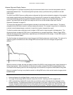
Radio paths over water or extremely flat ground may require optimization of antenna height at one end. This is
due to in-phase or out-of-phase reflections. Adjustment of antenna height by 1 to 3 meters may move the signal
from a null to a peak.
Long distance links may be obstructed by earth curvature, so the antenna height requirements must not only take
the height of obstructions and Fresnel Zone into account, but also earth bulge. The earth bulge is approximately
5 m (16.4 ft) at a link distance of 16 Km (10 mi).
In these cases, consult your supplier to take appropriate steps to maintain or optimize wireless link performance.


