


Tsunami MP.11 Antenna Installation
Copyright © 2006 Proxim Wireless Corporation. All rights reserved. 15
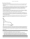
The definition of the 1
st
Fresnel zone is an imaginary boundary line offset along the direct signal path. This
boundary is defined as the point where if a signal were reflected between the two antennas, it would travel a
distance exactly one-half wavelength longer than the direct-path signal. Each succeeding Fresnel zone boundary
adds an additional half-wavelength to the reflected path distance between the antennas.
Signals reflected from any even-numbered Fresnel zone result in signal cancellation; those from odd-numbered
Fresnel zones add to the direct path signal.
The exact shape and width of the Fresnel Zone is determined by the path length and frequency of the radio
signal. The width as distance from the direct antenna beam is approximately 6 m (21 ft) in the middle of the
wireless link for a distance of 6.5 Km (4 mi) and a frequency of 5.8 GHz. This width also is the required clearance
of the antenna beam from obstacles in its path, to avoid loss of radio signal.
When any significant part of this zone is obstructed, a portion of the radio energy is lost, resulting in reduced
performance. Reduced performance also can occur when obstacles close to the antenna beam cause signal
reflections or noise that interfere with the radio signal.
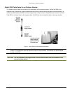
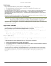
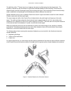
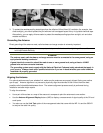
The following figure shows some typical examples of obstacles you must avoid for the directional antenna to
operate effectively:
a. Neighboring buildings
b. Trees or other obstructions
c. Power lines
For optimal performance, you must ensure that the type and placement of the antennas leave sufficient clearance
of the Fresnel Zone at the maximum width of the bulge, which is typically at the mid-point between the antennas.
Figure 2. Potential Obstacles for a Directional Antenna