


4 © 2011 Polk Audio—all rights reserved © 2011 Polk Audio—all rights reserved 5
ENGLISH
INTRODUCTION
Thank you for your purchase of a Polk Audio PA D Series amplifier. Each PA D Series amplifier is designed
to be the leader in its class offering the most power, advanced features, and extreme ease of use. In high-end
sound systems or high SPL systems, PA D Series amplifiers will give you years of trouble-free performance.
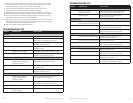
• PA D1000.1—1200W x 1 RMS @ 1 Ohm; 800W x 1 RMS @ 2 Ohms; 500W x 1 RMS @ 4 Ohms.
Note: Improper installation will not only limit the performance of your Polk Audio PA D Series amplifier but also
potentially compromise the reliability of this amplifier. To ensure proper sonic results and component reliability,
please refer to your authorized dealer for installation assistance or advice. If you decide to perform the installation
yourself, be sure to read the entire manual before beginning the installation (see Installation Guidelines on page 8).
RECORD THIS INFORMATION FOR YOUR RECORDS
Model:__________________________________________________
Serial Number:____________________________________________
Date of Purchase:__________________________________________
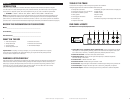
WHAT’S IN THE BOX
• PolkAudioAmplifier •RemoteLevelControl
• PhillipsScrews(8) •Remote Level Control Wire
•Owner’sManual •TerminalBlockAdaptor
• Online Registration Card
Important Note: If anything is missing or damaged, or if your Polk Audio amplifier fails to operate,
notify your dealer immediately. We recommend keeping your original carton and packing materials
in case you need to ship the unit in the future.
WARNING: LISTEN CAREFULLY
Polk Audio amplifiers, loudspeakers and subwoofers are capable of playing at extremely high volume levels,
which could cause serious or permanent hearing damage. Polk Audio accepts no liability for hearing loss,
bodily injury or property damage resulting from the misuse of its products. Keep these guidelines in mind
and always use your own good judgment when controlling volume. For more about safe volume levels,
go to: www.osha.gov/dts/osta/otm/noise/standards_more.html
TOOLS OF THE TRADE
Listed next are the majority of the tools required to perform an installation.
Having the proper tools will make the installation that much easier.
• Phillipsheadscrewdriver •Solderless,crimp-onconnectorsandacrimpingtool
• Electricdrilland3/16"and1/8"drillbits •Safetyglasses
• Permanentinkmarkerorpencil •DMMorVOM
• Safetyglasses •Nylontiestraps
• Wirestrippersandcutters •Wirecrimper
• Electricaltape •Grommetsforpassingwiresthroughmetalcarwalls
• AmplifierPowerWire
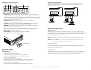
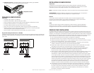
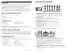
END PANEL LAYOUTS
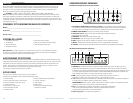
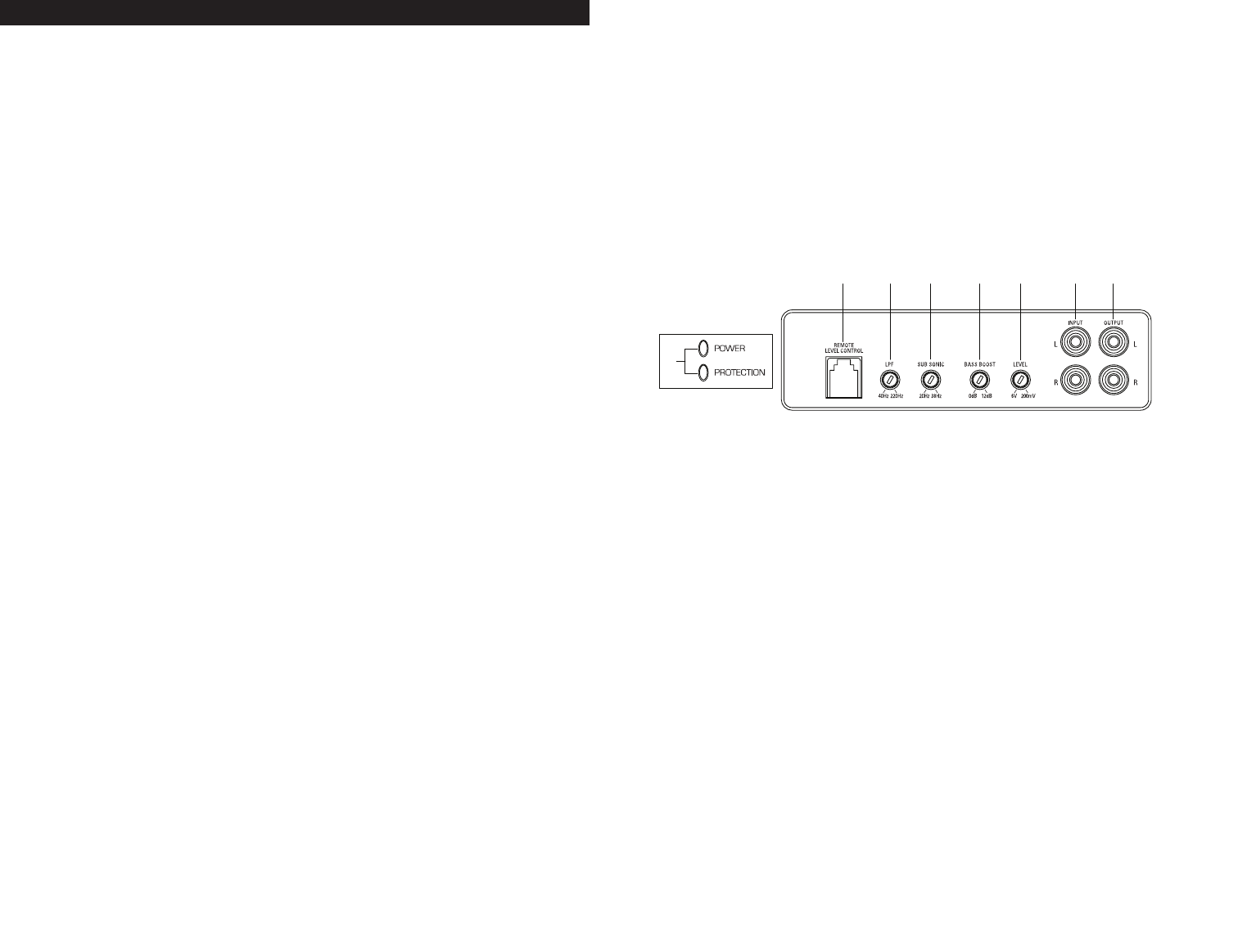
PA D1000.1 Line Level Inputs/Outputs/Controls
1. Status LEDs (on top of amplifier): Power and Protection—Power will illuminate to indicate
the amplifier is on and operating normally; protection will illuminate if the amplifier shuts down
due to short circuit, DC offset, or overheating detected by onboard protection circuitry.
2. Remote Level Control—Connects remote bass control module.
3. LPF Variable Control—Adjusts the low pass filter frequency to attenuate frequencies
above the setting on the control.
4. Sub Sonic Filter—Variablefrom20Hz-38Hz.
5. Bass Boost Control—Variablebassgainfrom0dB-12dB.
6. Level Control—Adjusts the gain of the channel to match the output voltage from your head unit.
7. Line Level Inputs—Accepts Line level input from a source unit, preamplifier, or equalizer.
8. Line Level Outputs—Provides a full range signal for easy connection to additional amplifiers.
L
R
L
INPUT OUTPUT
R
LPF
LPF
HPF LEVEL
BPF
FULL
HPF
X-OVER
HPF
X-OVER
FREQ x 10
FREQ x 1
FREQ x 10
FREQ x 1
20Hz400Hz 6V 200mV50Hz 500Hz
GND
12VREM
25A25A
LLRR
BRIDGED
L
R
L
R
LPFHPF LEVELLPFHPFLEVEL
HPF
BPF
FULL
HPF
BPF
FULL
ST
4CH
FRONT
REAR
X-OVER
X-OVER
FREQ x 10
FREQ x 1
FREQ x 10
FREQ x 1
50Hz 500Hz 50Hz 500Hz20Hz 400Hz 20Hz 400Hz6V 200mV 6V 200mV
CHANNEL
MODE
GND
12VREM
40A
35A
RL FL
RR
REAR
FRONT
FR
RR FR
RL FL
INPUT
SUB 1
SUB 2
SOURCE
SUB
INT
LEVEL
SUB
SONIC
LPF
REMOTE LEVEL CONTROL
INPUT
FR RR
FL RL
4CHST
CHANNEL
MODE
LPFHPF LEVEL
BPF
FULL
HPF
HPFFULL
HPF LEVEL
FRONT
REAR
6V 200mV
6V 200mV
20Hz 38Hz 40Hz 220Hz
40Hz 4000Hz 6V 200mV40Hz 400Hz80Hz4000Hz
SUB
GND
12VREM
40A40A
RL FL
SUB
RR FR
RR FR
SUB
RL FL
28
76543
PA D1000.1
1432 5
27654b4a3a
PA D2000.2
3b 1432 5
21211
PA D4000.4
4a 5a 9a 10a
4b 5b 9b 10b6 7 8
14323
8
5
2
1
PA D5000.5
109 11 15 1612 13 14
1432
1
1
1
3 4 6 75 5