


En
23
03
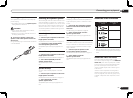
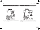
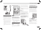
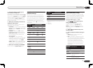
Connecting your equipment
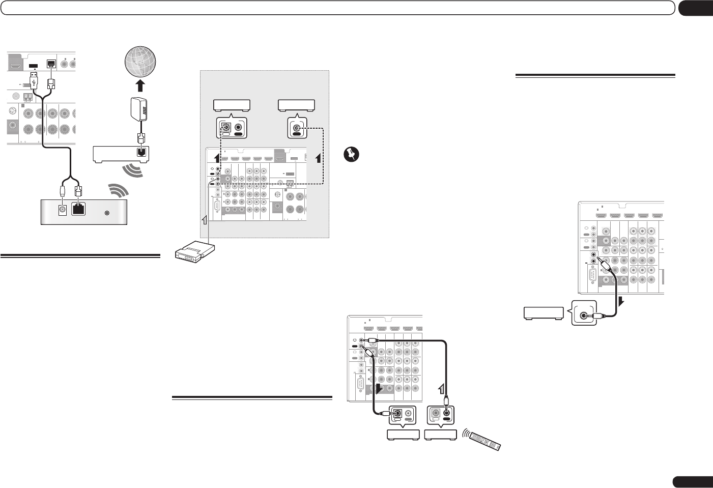
WAN
DC 5V WPS
Ethernet
U
NBAL
FRONT CENTER
SURROUN
D
IN
R L R
AM LOOP
(
CD
)(
DVD
)
COAXIAL
R
IUS
P
RE OUT
SPE
A
TENNA
ASSIGNABL
OUT
SUBWOOFER
IN
1
IN
2
CAUTION:
SPEAKER IMPEDANCE
6
-
16 .
ATTENTION:
ENCEINTE D’IMPEDANCE DE
6
-
16 .
A
DC OUTPUT
for WIRELESS LAN
(
OUTPUT 5
V
0.1 A MAX
)
ADAPTER PORT
(
OUTPUT 5 V 0.6 A MAX
)
(
10/100
)
LAN
Internet
Modem
Wireless LAN converter (AS-WL300)
Router
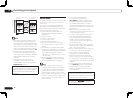
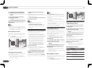
Connecting an IR receiver
If you keep your stereo components in a closed
cabinet or shelving unit, or you wish to use the
sub zone remote control in another zone, you
can use an optional IR receiver (such as a Niles
or Xantech unit) to control your system instead
of the remote sensor on the front panel of this
receiver.
! Remote operation may not be possible if direct
light from a strong fluorescent lamp is shining
on the IR receiver remote sensor window.
! Note that other manufacturers may not use
the IR terminology. Refer to the manual that
came with your component to check for IR
compatibility.
! If using two remote controls (at the same
time), the IR receiver’s remote sensor takes
priority over the remote sensor on the front
panel.
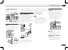
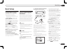
1 Connect the IR receiver sensor to the IR
IN jack on the rear of this receiver.
VIDEO
CONTROL
IR
RS-232C
COMPONENT
VIDEO
TV/SAT
IN
ZONE 2
DVR/
BDR
OUT
OUT
DVD ININ
VIDEO
IN
Y P
B
P
R
ASSIGN
ABLE
MONITOR
OUT
MONITOR
OUT
(
DVD
)
IN
1
(
DVR/
BDR
)
IN
2
OUT
IN
OUT
IN
2
1
HDMI
VIDEO IN
DVR/BDR
CD-R/TAPE
ZONE 2
IN
IN
IN
CD
L
R
L
R
IN
L
R
OUT OUT
DVD INBD IN
DVR/BDR IN
FM UNBAL
75
FRONT C
IN
R L
AM LOOP
TV/SAT VIDEO DVD
LAN
AUDIO
SIRIUS
PRE OUT
ANTENNA
OUT
SUBWOOFER
IN
1
ASSIGNABLE
1
CAUTION:
SPEAKER IMPEDANCE
6
-
16 .
ATTENTION
ENCEINTE D’IMPE
6
-
16 .
A
DC OUTPUT
for WIRELESS LAN
(
OUTPUT 5
V
0.1 A MAX
)
ADAPTER PORT
(
OUTPUT 5 V 0.6 A MAX
)
12 V
TRIGGER
TOTAL
150 mA
MAX)
(OUTPUT
12 V
IN
IR
IN OUT
CONTROL
Closet or shelving unit
Pioneer
component
Non-Pioneer
component
IR receiver
2 Connect the IR IN jack of another
component to the IR OUT jack on the rear
of this receiver to link it to the IR receiver.
Please see the manual supplied with your IR
receiver for the type of cable necessary for the
connection.
! If you want to link a Pioneer component to
the IR receiver, see Operating other Pioneer
components with this unit’s sensor on page
23 to connect to the CONTROL jacks instead
of the IR OUT jack.
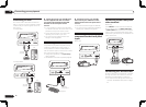
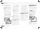
Operating other Pioneer
components with this unit’s
sensor
Many Pioneer components have SR CONTROL
jacks which can be used to link components
together so that you can use just the remote
sensor of one component. When you use a
remote control, the control signal is passed
along the chain to the appropriate component.
! If you want to control all your components
using this receiver’s remote control, see page
53.
! If you have connected a remote control to the
CONTROL IN jack (using a mini-plug cable),
you won’t be able to control this unit using the
remote sensor.
Important
! Note that if you use this feature, make sure
that you also have at least one set of analog
audio, video or HDMI jacks connected to
another component for grounding purposes.
1 Decide which component you want to
use the remote sensor of.
When you want to control any component in the
chain, this is the remote sensor at which you’ll
point the corresponding remote control.
2 Connect the CONTROL OUT jack of that
component to the CONTROL IN jack of
another Pioneer component.
Use a cable with a mono mini-plug on each end
for the connection.
VIDEO
CONTROL
IR
RS-232C
COMPONENT
VIDEO
TV/SAT
IN
ZONE 2
DVR/
BDR
OUT
OUT
DVD ININ
VIDEO
IN
Y P
B
P
R
ASSIGN
ABLE
MONITOR
OUT
MONITOR
OUT
(
DVD
)
IN
1
(
DVR/
BDR
)
IN
2
OUT
IN
OUT
IN
2
1
HDMI
VIDEO IN
DVR/BDR
CD-R/TAPE
ZONE 2
IN
IN
IN
CD
L
R
L
R
IN
L
R
OUT OUT
DVD INBD IN
DVR/B
D
TV/SAT VIDEO DVD
AUDIO
IN
1
ASSIGNABLE
1
12 V
TRIGGER
TOTAL
150 mA
MAX)
(OUTPUT
12 V
CONTROL
IN OUT
IN OUT
CONTROL
3 Continue the chain in the same way for
as many components as you have.
Switching components on and
off using the 12 volt trigger
You can connect components in your system
(such as a screen or projector) to this receiver
so that they switch on or off using 12 volt
triggers when you select an input function.
However, you must specify which input func-
tions switch on the trigger using the The Input
Setup menu on page 26 . Note that this will only
work with components that have a standby
mode.
HDMI
VIDEO
CONTROL
IR
RS-232C
COMPONENT
VIDEO
VIDEO IN
TV/SAT
IN
ZONE 2
DVR/BDR
CD-R/TAPE
ZONE 2
DVR/
BDR
OUT
OUT
DVD ININ
IN
IN
IN
CD
L
R
L
R
IN
L
R
OUT OUT
VIDEO
IN
DVD INBD IN
DVR/BDR IN
FM U
N
75
TV/SAT VIDEO DVDY P
B
P
R
(
O
0
AUDIO
SIRI
U
P
R
ANT
ASSIGN
ABLE
MONITOR
OUT
MONITOR
OUT
S
U
IN
1
(
DVD
)
IN
1
(
DVR/
BDR
)
IN
2
ASSIGNABLE
1
OUT
IN
OUT
IN
2
1
12 V
TRIGGER
TOTAL
150 mA
MAX)
(OUTPUT
12 V
12 V TRIGGER
INPUT
% Connect the 12 V TRIGGER jack of this
receiver to the 12 V trigger of another
component.
Use a cable with a mono mini-plug on each end
for the connection.
After you’ve specified the input functions that
will switch on the trigger, you’ll be able to
switch the component on or off just by pressing
the input function(s) you’ve set on page 26.