


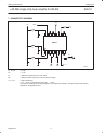
Philips Semiconductors Product data
SA2411+20 dBm single chip linear amplifier for WLAN
2003 Feb 07
8
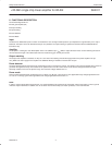
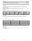
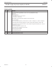
Table 6. SA2411 Detector specification
T
amb
= 25 °C, V
CC
= 3.0 V
Specification Condition, Remarks Min Nom Max Units
GENERAL
Detector sensitivity With 5 kΩ load resistor to ground – 49 – mW/V
2
Detector accuracy per sample At 16 dBm –40 °C to +80 °C; from 2.7 V to 3.6 V – 0.3 – dB
Absolute accuracy From sample to sample – 0.5 – dB
Detector quadratic factor – 1.5 – –
Detector settling time From 10% to 90% of final value – 500 – ns
Spread from sample to sample 20 dBm output power – 1 – dB
Absolute detector voltage 19 dBm output power – 1.4 – V
Absolute detector voltage error From –30 °C to +80 °C;
from 2.7 V to 3.6 V at 19 dBm output power
– 0.15 – V
Detector power range +10 – +21 dBm
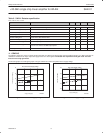
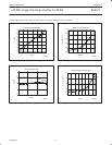
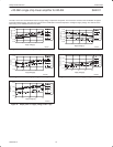
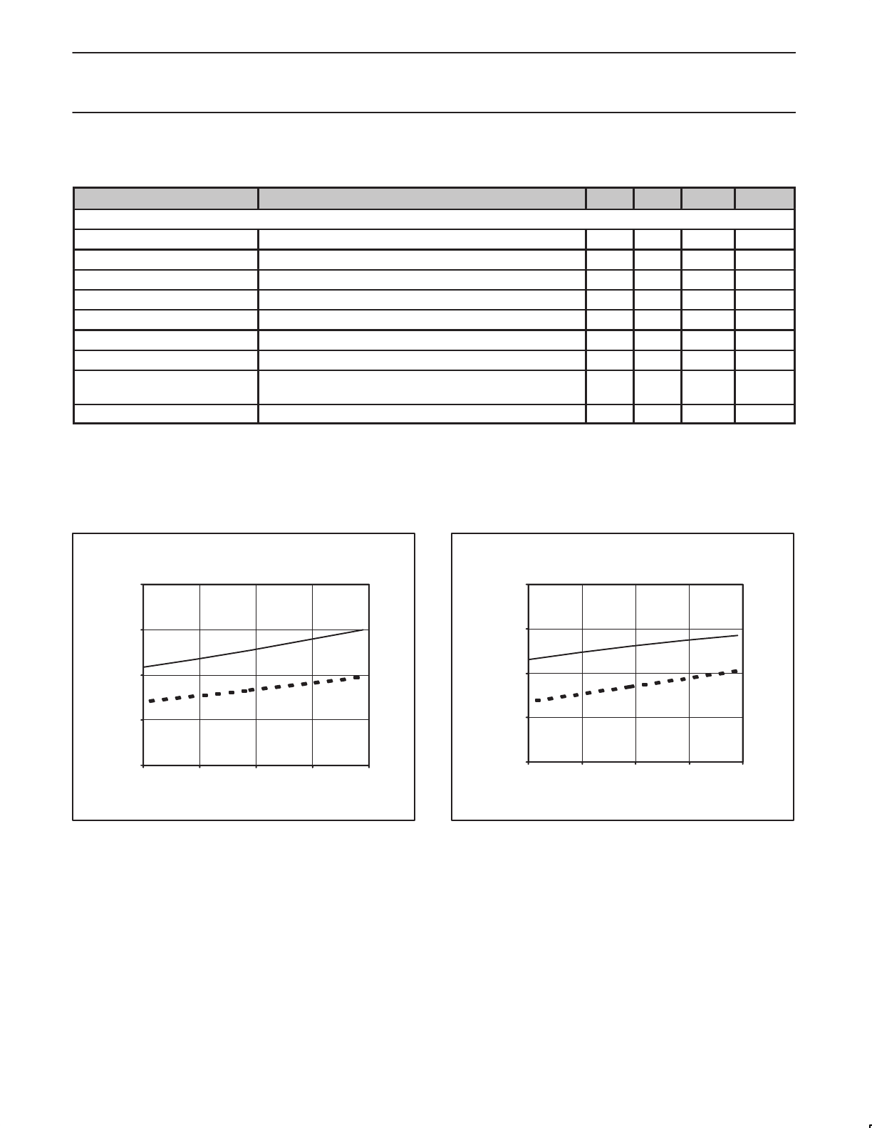
11. GRAPHS
The following graphs are only for a typical sample measured on a SA2411 test board under nominal condition applying an 11Mb/s CCK 802.11b
modulation. Corrections for input, output and supply losses have been applied. The dotted lines represent the low gain mode. The solid
lines are for the high gain mode.
The first two graphs are small signal graphs. The gain and the DC currents are plotted versus supply voltage.
small signal current[mA]]
SR02464
DC current versus Supply Voltage
10
20
30
40
50
2.7 2.9 3.1 3.3 3.5
Supply Voltage[V]
Figure 3. DC current vs. supply voltage
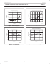
SR02465
Gain versus Supply Voltage
10.0
12.0
14.0
16.0
18.0
2.7 2.9 3.1 3.3 3.5
Supply Voltage[V]
Small signal gain[dB]]
Figure 4. Gain vs. supply voltage