


Philips Semiconductors Product data
SA2411+20 dBm single chip linear amplifier for WLAN
2003 Feb 07
5
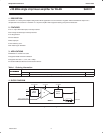
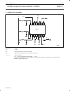
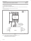
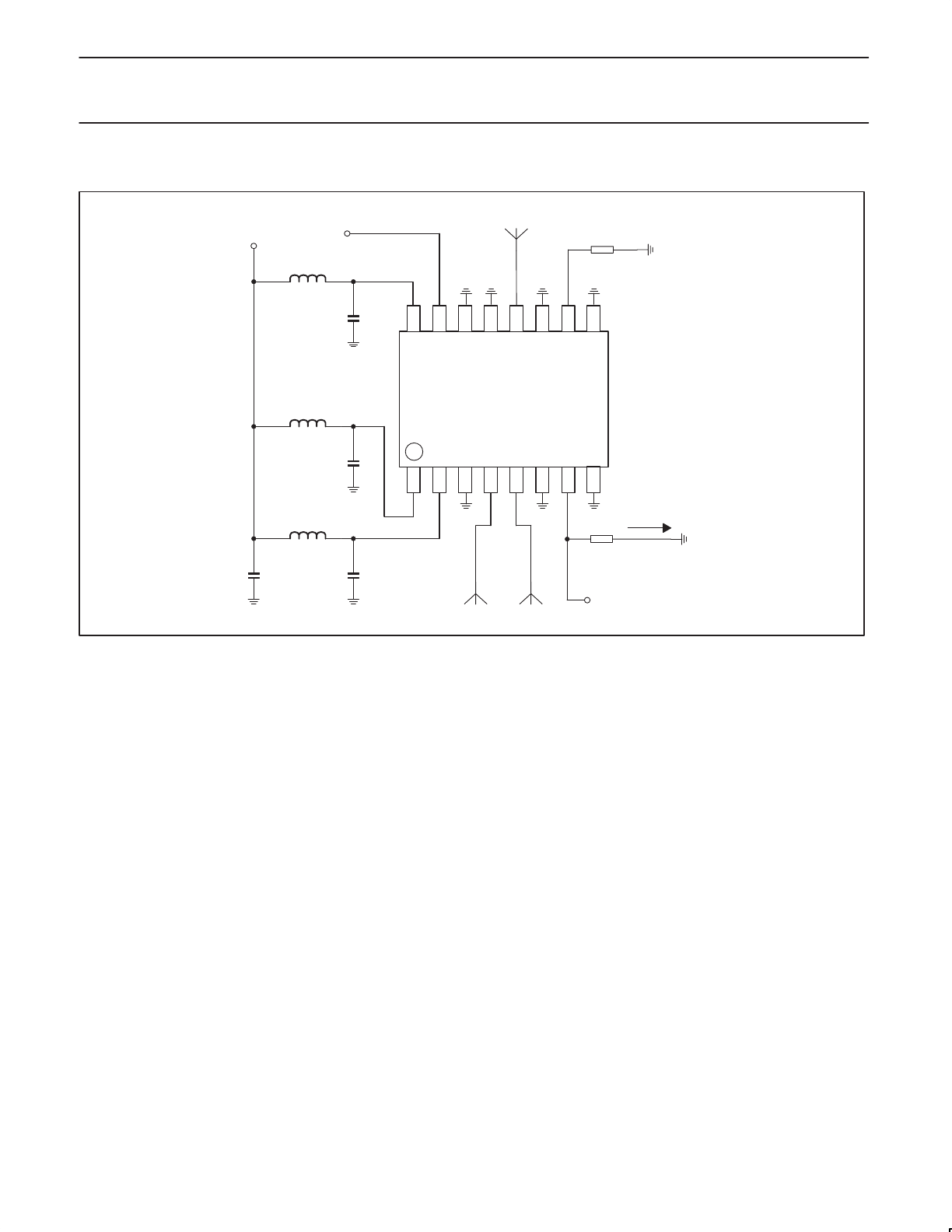
7. CONNECTIVITY DIAGRAM
SR02385
C2
C1
C4 C3
L3
L2
PWRUP
RFin
ANT
L1
VDD
VDD
GND
IN+
IN–
GND
DET
GND
VDD
PwrUp
GND
GND
ANT
GND
MODE
GND
RFin
R1
R2
Idet.
V
det
V
DD
SA2411
C1, C2, C3 = 5.6 pF
C4 = 10 nF
R1 = optional connect to ground via 0 W resistor.
R2 = optional resistor to ground to convert current into voltage
L1, L2, L3 = Optional inductors
1 nH … 10 nH, or microstrip lines with length 1 … 10 mm.
No inductors and directly connecting all supplies to V
DD
might cause problems. The optimal values of the inductors
depends on the application board.