


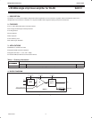

Philips Semiconductors Product data
SA2411+20 dBm single chip linear amplifier for WLAN
2003 Feb 07
14
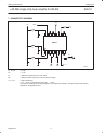
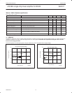
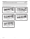
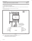
12. APPLICATION WITH THE SA2400A
Next diagram is the application of the SA2400A with the SA2411.
The interface is simple. Two equal microstrip lines connect the SA2400A with the SA2411. The length of this connection should be kept to a
minimum.
The supply for the open collectors of the SA2400A is provided via pin 2 of the SA2411.
C2 is for supply voltage decoupling.
SR02487
A_GND
TX_HI
A_V
TX_OUT_LO
SA2400A
DD
A_GND
TX_OUT_HI_P
TX_OUT_HI_M
A_GND
SEN
SDATA
SCLK
TX/RX
TX_IN_I_P/
TX_DATA_I
TX_IN_I_M/
TX_DATA_Q
TX_IN_Q_P
TX_IN_Q_M
AGCRESET
AGCSET
IDCOUT
A_GND
1
2
3
4
48 47 46 45 44 43 42 41 40 39 38 37
36
35
34
33
VDD_MAIN
VDD_DRIVER
IN+
IN–
GND
DETECTOR
GND
PWRUP
GND
RF_GND
ANT
GND
MODE
GND
GND
VDD_BIAS
SA2411
16 15 14 13 12 11 10 9
12345678
V
DD
PWRUP
I
detector
C2
3-WIRE BUS
RF connection
Other connection
Figure 25.
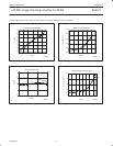
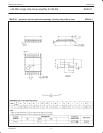
NOTE: A suggested starting point for designing the coupled microstrip lines:
Length = 1/18 λ. Width = 12 mils, Separation = 5 mils with the Dielectric constant = 4.6.
This should result in Z
even
= 150 Ω, Z
o
= 75 Ω, and Z
odd
= 30 Ω.
There should be no ground plane under the microstrip lines.