


C1648M (4/05) 17
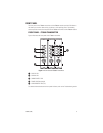
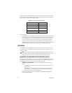
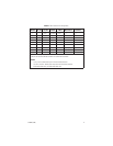
Table B.
Data Connector Pin Assignments
Pin
Number RS-232 RS-422
RS-485
2-Wire
RS-485
4-Wire Manchester Bi-Phase
1— Out+ In+/Out+ Out+ — —
2— Out- In-/Out- Out- — —
3— In+ — In+ In+ (W) In+
4— In- — In- In- (B) In-
5In — — — — —
6 Out — — — — —
7— ——— Out+ (W) Out+
8— ——— Out- (B) Out-
9 Ground —* —* —* Shield Shield
*Ground may be required based on conditions of installation. Refer to the current version of
EIA/TIA-422 and EIA/TIA-485 standards for additional information.
NOTES:
• In, In+, and In- denote data input to the transmitter/receiver.
• Out, Out+, and Out- denote data output from the transmitter/receiver.
•W denotes white wire, and B denotes black wire.