


14 C1648M (4/05)
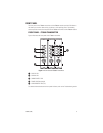
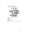
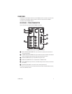
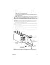
With the FT85081 transmitter/FR85081 receiver powered off, turn the Data Selection switch
using a screwdriver until the number representing the required data communication is selected.
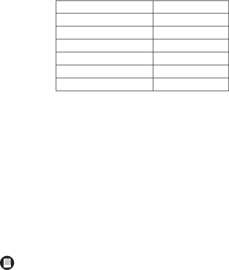
Refer to Table A for Data Selection switch settings.
Note the following:
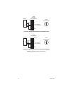
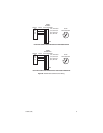
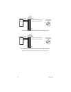
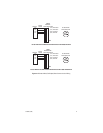
• The FT85081 transmitter/FR85081 receiver allows data translation between RS-232 and
RS-422 signal levels. Consequently, the Data Selection switch can be set to 0 (RS-232)
on the transmitter and to 1 (RS-422) on the receiver. Conversely, the Data Selection
switch can be set to 1 (RS-422) on the transmitter and to 0 (RS-232) on the receiver.
• If you wish to change the data communication setting after the FT85081 transmitter/
FR85081 receiver has been powered on, power off the transmitter/receiver, change the
data communication setting, and then power on the transmitter/receiver again.
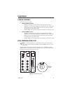
MOUNTING
The FT85081 transmitter/FR85081 receiver can be mounted into a rack or can be used as a
standalone module. As a standalone module, the unit can be placed on a desktop or can be
mounted to a wall.
NOTE:
As a matter of convenience, it is recommended that you set the desired data
communication before mounting the FT85081 transmitter/FR85081 receiver. To set the
desired data communication, refer to the
Data Communication Setup
section.
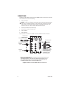
MOUNTING THE TRANSMITTER/RECEIVER INTO A RACK
The FT85081 transmitter/FR85081 receiver can be installed into the RK5000 Series rack mount
chassis, which can be mounted into an industry-standard 19-inch (48.26 cm) equipment rack.
The RK5000 Series rack mount chassis includes the following models:
•
RK5000PS-3U and RK5000-3U:
Designed to accommodate fiber optic modules as
follows:
– The RK5000PS-3U rack mount chassis provides 12 single-width module slots and
a power supply.
– The RK5000-3U rack mount chassis provides 14 single-width module slots (a
power supply is not included). Power to the modules can be supplied using the
optional external power supply (EPS5000-120).
For additional information, refer to the RK5000PS-3U/RK5000-3U Fiber Rack Mount
Chassis Installation manual.
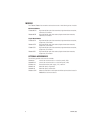
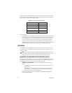
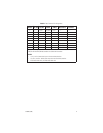
Table A.
Data Selection Switch Settings
Data Selection Switch Setting
RS-232 0 (default setting)
RS-422 1
RS-485 2-Wire 2
RS-485 4-Wire 3
Manchester/Bi-Phase 4
Not used 5-9