


C1648M (4/05) 13
Installation
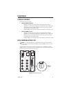
PACKAGE CONTENTS
The following items are supplied:
• With the FT85081 transmitter:
1 Regulated switching power supply with four plug adapters (North American,
Australian, U.K., and European configurations); 100-240 VAC input, 12 VDC output
1Wall clip with two 4-40 x .250-inch Phillips pan head screws with lock washers
(for attachment of single module to wall)
1 FT85081/FR85081 Fiber Transmitter and Receiver Installation manual (this manual)
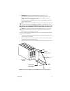
• With the FR85081 receiver:
1 Regulated switching power supply with four plug adapters (North American,
Australian, U.K., and European configurations); 100-240 VAC input, 12 VDC output
1Wall clip with two 4-40 x .250-inch Phillips pan head screws with lock washers
(for attachment of single module to wall)
1 FT85081/FR85081 Fiber Transmitter and Receiver Installation manual (this manual)
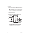
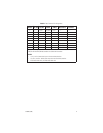
DATA COMMUNICATION SETUP
NOTE:
As a matter of convenience, it is recommended that you set the desired data
communication
before
mounting the FT85081 transmitter/FR85081 receiver into a rack
or onto a wall.
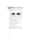
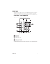
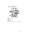
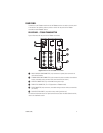
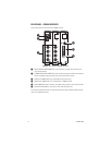
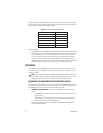
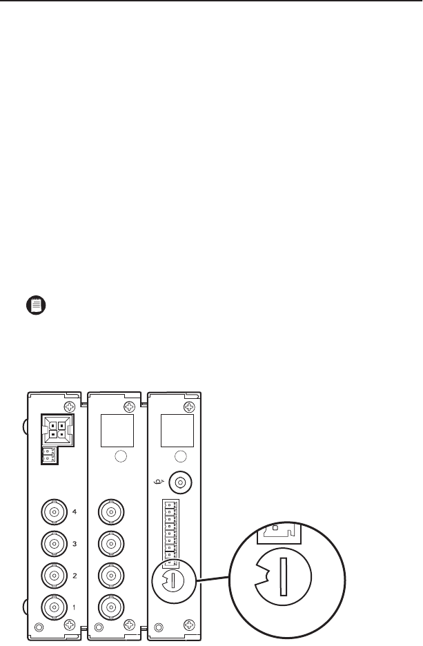
The Data Selection switch, which is located on the rear panel of the FT85081 transmitter/
FR85081 receiver, is a 10-position rotary switch that allows you to set the data communication
required for the transfer of data (refer to Figure 6).
Figure 6.
Data Selection Switch
1
2
3
4
5
6
7
8
GND
5
6
7
8
DATA
SELECTION
SWITCH
0
1
2
3
4
5
6
7
8
9
0
1
2
3
4
5
6
7
8
9