


20 C2649M (9/07)
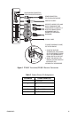
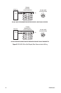
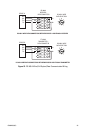
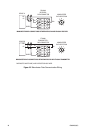
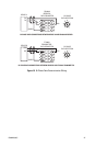
Table D. Data Connector Pin Assignments
Pin
Number RS-232 RS-422
RS-485
2-Wire
RS-485
4-Wire Manchester Bi-Phase
1 TX+ (Out+) T+/R+ (Out+/In+) TX+ (Out+) TX+ (Out+) (W) TX+ (Out+)
2 TX-(Out-) T-/R-(Out-/In-) TX- (Out-) TX- (Out-) (B) TX- (Out-)
3 — RX+ (In+) — RX+ (In+) RX+ (In+) (W) RX+ (In+)
4 — RX- (In-) — RX- (In-) RX- (In-) (B) RX- (In-)
5RX (In)— — — — —
6TX (Out)— — — — —
7 or 8 Ground —* —* —* Shield Shield
*Ground may be required based on conditions of installation. Refer to the current version of EIA/TIA-422
and EIA/TIA-485 standards for additional information.
NOTES:
• TX (Out), TX+ (Out+), TX- (Out-), T+ (Out+), and T- (Out-) denote data output from the transmitter/
receiver.
• RX (In), RX+ (In+), RX- (In-), R+ (In+), and R- (In-) denote data input to the transmitter/receiver.
• W denotes white wire, and B denotes black wire.
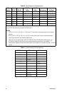
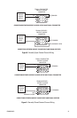
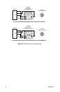
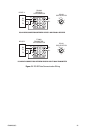
• Data ports are not terminated. For RS-422, RS-485 2-Wire, RS-485 4-Wire, Manchester, and
Bi-Phase data signals, termination may be required based on conditions of installation. If
termination is required, terminate the data signal at the endpoint of the data bus using a 120-ohm
resistor.
Table E. Audio Connector Pin Assignments
Pin Number Balanced Unbalanced
1In, Left+—
2 In, Right+ —
3In, Left-—
4 In, Right- —
5— In, Left
6 — In, Right
7 or 8 — Shield
9 Out, Left+ Out, Left
10 Out, Right+ Out, Right
11 Out, Left- —
12 Out, Right- —