


C2649M (9/07) 11
REAR PANEL
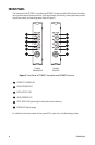
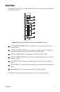
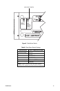
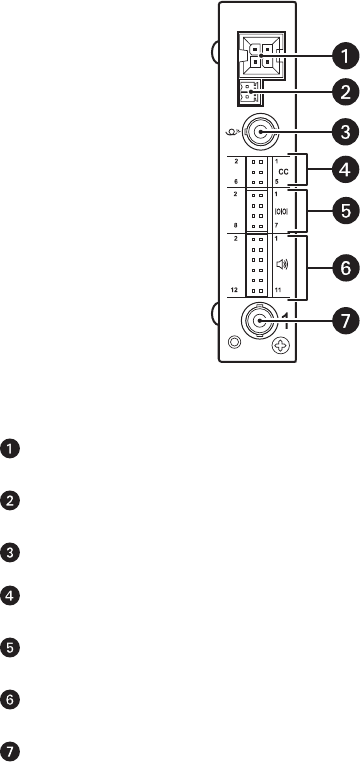
All connections to the FT106011 transmitter and FR106011 receiver are made to the rear panel of the
modules (refer to Figure 3).
Figure 3. Rear Panel of FT106011 Transmitter and FR106011 Receiver
For additional information about rear-panel connections, refer to the Installation section.
RACK POWER/ALARM CONNECTOR, 4-pin connector for power/alarm connection of rack-
mounted module
STAND-ALONE POWER CONNECTOR, 2-pin connector for power connection of stand-alone
module; removable mating connector with screw terminals (not shown)
FIBER OPTIC CONNECTOR, ST or FC (dependent on FT106011/FR106011 model)
CONTACT CLOSURE CONNECTOR, 6-pin connector; removable mating connector with tension
clamps (not shown)
DATA CONNECTOR, 8-pin connector; removable mating connector with tension clamps (not
shown)
AUDIO CONNECTOR, 12-pin connector; removable mating connector with tension clamps (not
shown)
BNC CONNECTOR, 75-ohm analog video input (FT106011)/output (FR106011)