


8
Outlaw Audio
Owner’s Manual
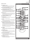
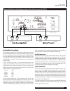
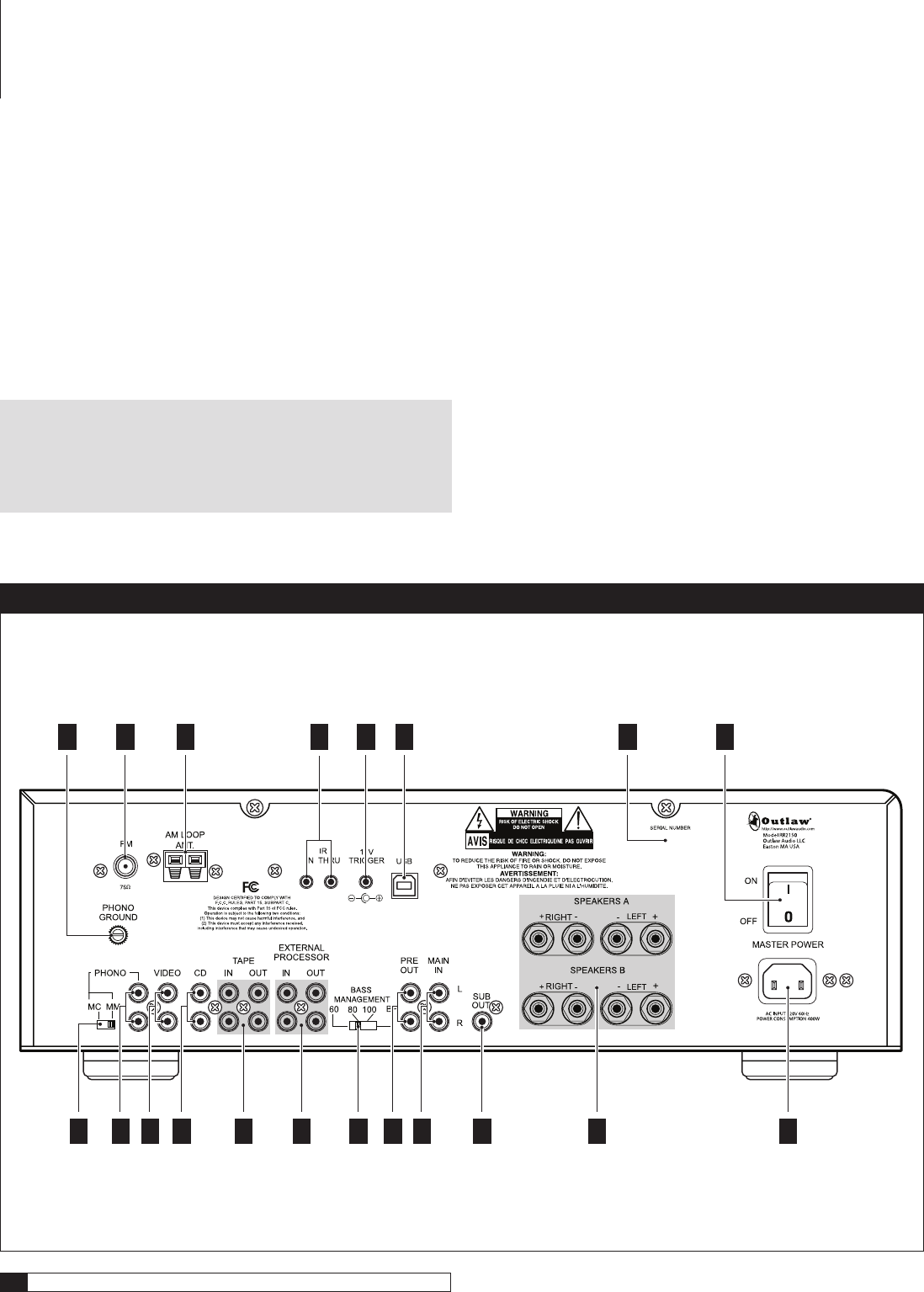
RP14 External Processor Loop connections (see pages 11, 13)
Connect an external processor (equalizer, electronic crossover, surround
processor, etc.) to these jacks. These outputs are also fixed-level.
RP15 Bass Management selector switch (see page 15)
This switch lets you adjust the internal crossover (bass management
system) to route user-selected low frequencies to the subwoofer output
(RP18) while the rest of the audio signal is sent to the amplifier and
then to the main loudspeakers.
RP16 Preamplifier outputs (see pages 16-17)
These outputs allow you to connect a high output power amplifier if
needed. Simply remove the jumpers and connect the preamp outputs to
the inputs of the additional amplifier.
NOTE: Removing the jumpers ordinarily means that the RR 2150’s
internal amplifier does not receive a signal and thus can not send any
output to the speakers you have connected to it. In unusual circum-
stances, you can use shielded “Y” cords to connect both the internal
amplifier and another amplifier to the receiver’s preamp section.
RP17 Main amp inputs (see pages 16-17)
These inputs are normally connected to the preamplifier outputs by
jumpers. (See RP16 above.)
RP18 Subwoofer line level output (see pages 14-15)
Connect a powered subwoofer to this output. Make sure you’ve set the Bass
Management selector switch (RP15) correctly. The output from this con-
nector is variable and controlled by the Master Volume setting (FP20).
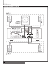
RP19 Loudspeaker outputs (see pages 13-15)
Use these binding posts to connect your primary (Speakers A) and
secondary (Speakers B) loudspeakers to the RR 2150.
RP20 AC socket (see page 16)
Connect the supplied AC power cord to this socket before turning on the
Master Power Switch (RP8).
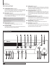
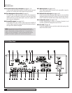
RR 2150 Rear Panel
RR2150 Rear Panel
RP
1
RP
2
RP
3
RP
4
RP
5
RP
7
RP
9
RP
13
RP
14
RP
19
RP
20
RP
18
RP
6
RP
10
RP
11
RP
12
RP
15
RP
16
RP
17
RP
8