


7
Front & Rear Panels
—Continued
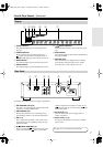
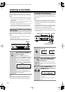
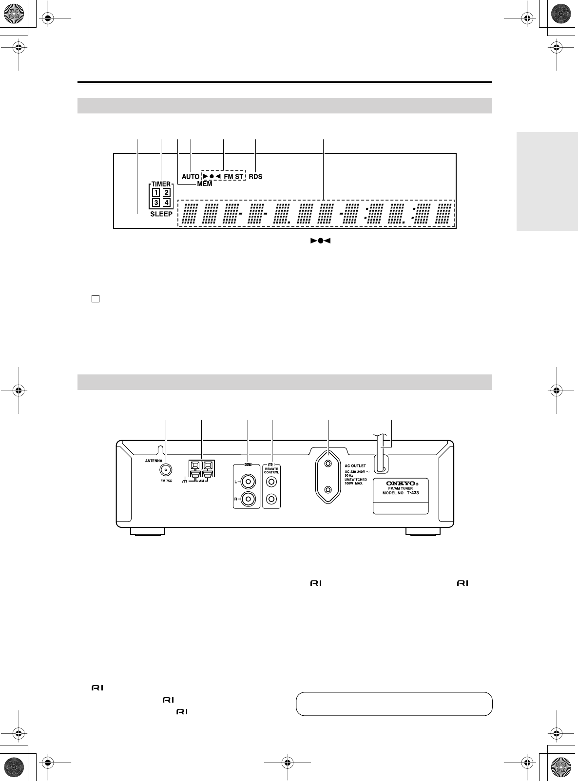
A
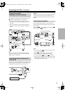
SLEEP indicator
This indicator lights up when the sleep timer has
been set.
B
TIMER indicators
These indicators show the status of the timers.
:
Lights up when timed recording has been set.
Numbers 1–4:
Lights up when a timer has been set.
C
MEM indicator
This indicator lights up when storing radio presets.
D
AUTO indicator
This indicator lights up when the FM mode is Auto.
E
/FM ST indicators
These indicators show the status of the radio recep-
tion.
F
RDS indicator
This indicator lights up when tuned to an FM station
that supports RDS.
G
Message area
Various information is displayed here, including
preset number, tuning frequency, time, volume
level, sleep time, mode settings, and so on.
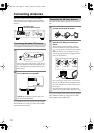
For detailed information, refer to the pages in parentheses.
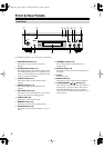
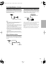
A
FM ANTENNA (75
Ω
) (12)
This jack is for connecting the supplied indoor FM
antenna or an outdoor FM antenna.
B
AM ANTENNA (12)
These push terminals are for connecting the sup-
plied AM loop antenna or an outdoor AM antenna.
C
OUT (11)
These output jacks should be connected to an ana-
log audio input on the amplifier by using the sup-
plied audio cable.
D
REMOTE CONTROL (11)
These two identical (Remote Interactive) jacks
can be connected to the jacks on your other
Onkyo components for interactive control. To use
, the T-433 must be connected with an cable
and an audio cable.
E
AC OUTLET (11)
This AC outlet can be used to supply power to
another component.
F
Power cord (11, 14)
The power cord should be connected to a suitable
power source.
Display
21 3 5 64 7
Rear Panel
1 3 42 5 6
See pages 10–13 for connection information.
*En_T433_02.fm Page 7 Tuesday, February 15, 2005 3:09 PM